





Luowave LFTX/RX-LW: What You Need to Add HF to an N210 or X310
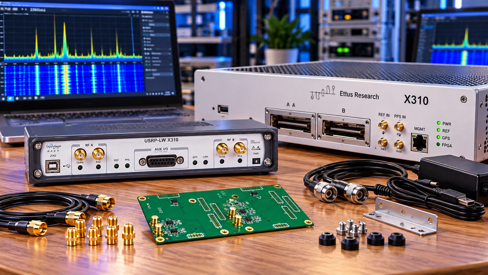
Adding HF with the Luowave LFTX/RX-LW starts with confirming the receive and transmit boards you will actually receive, then specifying filtering, RF protection and the host data path. The manufacturer's 0–30 MHz coverage claim is not a complete antenna-to-software system specification.
Our LFTX/RX-LW listing is intended for N210 and X310 platforms. LUOWAVE confirms that platform positioning, but the combined product name should not be treated as proof that one order includes every TX and RX component.
What changes when you add an HF frontend?
A modular N210 or X310 has converters, digital processing and a host interface. Its installed RF daughterboard determines how external signals reach those converters. A high-level chassis description such as DC–6 GHz does not mean every fitted daughterboard covers that entire range.
LF-style boards provide a direct low-frequency interface rather than a conventional tunable RF mixer frontend. An external HF upconverter is therefore not inherently required for the intended direct-HF application. You still need suitable signal conditioning and the correct software mode.
The UHD reference documentation distinguishes LFRX receive and LFTX transmit operation, including real-signal and paired I/Q modes. These reference-board concepts explain the architecture; confirm which modes the supplied LW hardware and driver expose.
Specify receive-only or transmit-and-receive
| Project | Required direction | Additional RF needs |
|---|---|---|
| HF monitoring | Confirmed LF receive hardware | Antenna, preselection, protection and controlled input level |
| Conducted waveform generation | Confirmed LF transmit hardware | Reconstruction filtering, attenuation and a suitable load or analyser |
| Two-way HF experiment | Both directions, explicitly included | Isolation, switching or duplex arrangement, plus filtering for each path |
For the purchase order, ask whether the offer contains an LFTX board, an LFRX board, a pair or a combined assembly, and request the part numbers. Also confirm motherboard mounting positions, panel adapters and internal cables. The slash in the listing title does not settle those questions.
A practical parts list
- One compatible N210 or X310-class host, with its correct power supply.
- The confirmed LF receive and/or transmit hardware for the intended task.
- A computer, supported driver and matching FPGA image.
- Gigabit Ethernet for the N210, or an appropriately specified X310 host connection.
- Correct RF cables, panel connections and adapters for the supplied assembly.
- HF filtering, attenuation, DC handling and protection appropriate to the actual signals.
- A known signal source for commissioning; transmit work also needs suitable measurement equipment and a load.
Do not assume that an external amplifier is necessary. Establish the received signal level and noise situation first. Added gain can worsen overload when strong broadcast or local signals reach a wideband direct input.
Filtering is part of the system design
On receive, use a low-pass or band-pass arrangement suited to the frequencies you want and the converter's actual sampling configuration. Energy outside the intended band can cause aliasing or overload. A software filter applied after sampling cannot undo analogue clipping.
For an antenna installation, also consider static discharge, nearby transmitters and whether DC can appear on the cable. Obtain the LW board's input limits and DC-coupling details before selecting a protection circuit or connecting unfamiliar equipment.
On transmit, plan reconstruction filtering to suppress unwanted DAC images and a measurement of the resulting spectrum. An HF output is not a complete amateur-radio transmitter or power amplifier. Any external PA adds requirements for drive level, filtering, thermal management and legal operation.
Separate RF coverage from stream bandwidth
A 0–30 MHz frontend range does not guarantee that your host can receive the whole range simultaneously in every mode. The N2xx documentation describes the Gigabit Ethernet platform; the selected sample representation and data rate remain transport constraints.
For illustration, complex sc16 uses four bytes per sample. A 25 MS/s stream carries 100 MB/s of sample payload; 30 MS/s carries 120 MB/s before Ethernet and transport overhead. Those calculations explain why analogue coverage cannot be translated directly into an unrestricted whole-HF recording promise.
Real-input and paired I/Q modes also map physical ports differently. Two analogue connections can represent I and Q of one complex signal rather than two independent ordinary receivers. Check the enumerated subdevices instead of counting connectors.
Configure and verify one path at a time
- Power down, observe ESD precautions and install the confirmed board and cable set.
- Probe the radio and save the daughterboard identification and available subdevices.
- Select the intended real or I/Q mode using the supported driver configuration.
- Start at a modest sample rate with a known low-level HF signal.
- Check frequency placement, signal images and the effect of input attenuation.
- Increase sample rate only after the stream is stable and the analogue path behaves as expected.
A frontend without tunable elements may not respond to gain and tuning controls in the way a mixer-based daughterboard does. Use the actual enumerated controls. If a signal moves incorrectly, investigate mode, sample rate and aliasing before changing the antenna or adding gain.
Frequently asked questions
Does the product name guarantee both TX and RX boards?
No. Obtain the package composition and part numbers in the quotation before buying for a two-way experiment.
Do I need a separate HF upconverter?
Not inherently for a supported direct-HF configuration. External conversion is a separate design choice, not an automatic accessory requirement.
Is the entire 0–30 MHz range equally useful?
Do not assume that. DC behaviour, low-frequency response, filtering and coupling need revision-specific documentation and measurement.
Can I transmit directly into an antenna?
Only after establishing output limits, filtering, matching and authorisation. Begin with a properly attenuated conducted setup.
Use our quote system with your motherboard model, required directions, HF bands and capture bandwidth. Ask for the boards and connection parts as explicit line items.
Shop products for this guide
Explore relevant products from our store.
No posts found
Write a review






We support all major card and digital payment options. More local methods are available and shown during checkout.
You enter into a binding sales contract once you have received an 'order confirmation and sales receipt' email from us, in line with our Sales & Delivery conditions. Therefore, sdrstore.eu has the right to cancel your order in the event of technical problems, delivery failure, Fair use policy and other similar situations.






Your payments are protected by advanced encryption and 3-D Secure authentication for safe online shopping.