





Full-Duplex QPSK with bladeRF: GNU Radio Flowgraph and Hardware Checklist
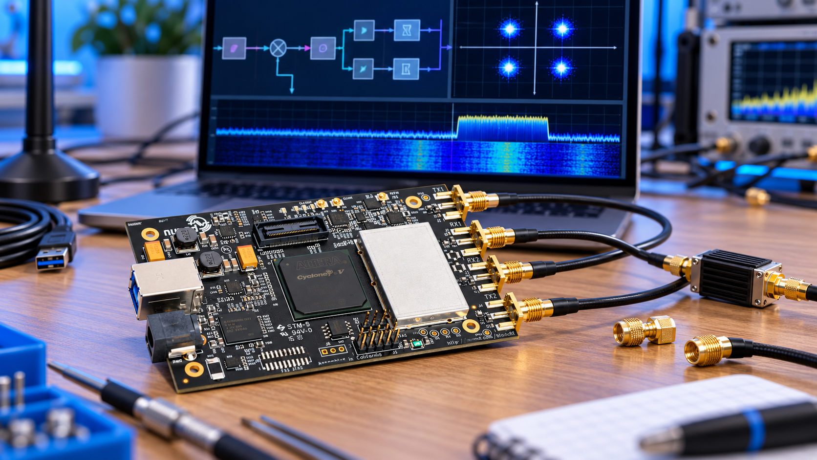
One bladeRF 2.0 micro can transmit a QPSK waveform while receiving through a separate RF port. Begin with a conducted, attenuated loopback and a modest sample rate. Prove modulation and decoding in software first, then add the radio without changing the entire modem at once.
This tutorial gives a proposed GNU Radio Companion flowgraph recipe for our bladeRF xA4 or xA9. It has not been hardware-tested here. The larger FPGA is not required merely because ordinary host-side GNU Radio blocks are used.
Prepare the hardware and software
- One bladeRF 2.0 micro, suitable enclosure and a known-good USB 3 data cable.
- A host with compatible GNU Radio, libbladeRF and gr-osmosdr builds.
- The correct xA4 or xA9 hosted FPGA image and compatible firmware.
- Coax and fixed attenuators suitable for the chosen frequency and worst-case output.
- Suitable 50-ohm loads for any active transmit paths not connected to the test fixture.
- A power measurement method when verifying the external RF path.
Follow our bladeRF setup guide first. Confirm bladeRF-cli can identify the board and report firmware and FPGA versions. Close other programs before opening the radio from GNU Radio.
Protect the receiver before enabling TX
Never connect the transmitter directly to the receiver. Determine attenuation from the maximum possible output and the permitted input for your exact hardware. Use received power = transmit power − attenuation − cable loss, and retain margin below the receiver's damage and compression limits.
For illustration only, +8 dBm followed by 40 dB attenuation gives approximately −32 dBm before cable loss. This is arithmetic, not a measured output or universal safe configuration. Confirm the actual limits and attenuator power rating. Disable bias tees for an ordinary passive loopback path.
Keep testing conducted or inside a suitable shielded arrangement. Over-the-air operation requires appropriate authorisation and frequency, power and spectral compliance.
Use explicit modem parameters
| Parameter | Proposed starting value |
|---|---|
| Radio sample rate | 2 MS/s, subject to actual rate readback |
| Symbol rate | 500 ksymbols/s |
| Samples per symbol | 4 |
| Modulation | Four phases: 1, j, −1, −j |
| Differential coding | Modulo 4 at TX and RX |
| RRC roll-off | 0.35 |
| RRC filter length | 45 taps at the 2 MS/s sample rate |
| RF carrier | A frequency supported by both paths and the conducted fixture |
The nominal uncoded bit rate is 500,000 × 2 = 1 Mbit/s before framing or coding overhead. The approximate raised-cosine occupied bandwidth is 500 kHz × 1.35 = 675 kHz. These are design calculations, not measured throughput or a regulatory occupied-bandwidth test.
Build the transmit branch
Connect a repeating Vector Source of byte-valued symbols 0–3 to a Differential Encoder with modulus 4, then Chunks to Symbols using the table 1, j, −1, −j. Follow it with an Interpolating FIR Filter at interpolation 4, using root-raised-cosine taps, then a Multiply Const amplitude control and an Osmocom Sink.
For GNU Radio's root_raised_cosine tap generator, use gain 4, sampling frequency 2e6, symbol rate 500e3, alpha 0.35 and 45 taps for the TX interpolator. Start with a small amplitude such as 0.1 and inspect the waveform for clipping. Digital amplitude and radio TX gain are separate controls.
Use a sufficiently long known sequence containing all four symbols. A short repetitive pattern can make alignment ambiguous. Define the source as symbols, not packed bytes, so no hidden unpacking or Gray-mapping step changes the intended alphabet.
Build the receive branch
Connect an Osmocom Source to amplitude normalisation or a conservatively configured AGC, then a matched RRC FIR Filter with decimation 1. Generate its taps with gain 1 and the same sample rate, symbol rate, roll-off and length as above.
Follow the matched filter with Symbol Sync configured for four input samples per symbol and one output sample per symbol. A Gardner timing-error detector and loop bandwidth around 0.02 are proposed starting choices; review detector gain and other parameters for the installed block version.
Next use a Costas Loop with order 4, starting loop bandwidth around 0.03, then a Constellation Decoder using the exact ordered points 1, j, −1, −j. Finish with a Differential Decoder of modulus 4. GNU Radio's Costas Loop documentation identifies order 4 for QPSK; the PSK tutorial explains timing and carrier recovery.
The explicit phase ordering makes constant quarter-turn carrier ambiguity cancel after differential decoding. Do not silently substitute a different constellation mapping or add a second differential stage.
Connect both radio blocks consistently
Put source and sink in the same flowgraph and select the same bladeRF, for example with bladerf=0 when only one is connected. Use one RX and one TX channel, matching sample rates and the same carrier for local loopback. Verify selected RF port labels against the physical connectors.
Nuand documents the device-selection arguments. Set conservative gains and a supported analogue bandwidth sufficient for the waveform, then read back actual settings. Hardware source and sink blocks pace this graph; do not add a Throttle block to the hardware path.
Verify in software, then through RF
- Replace the radio path with a simulated channel and a Throttle for that software-only test.
- Confirm the decoded symbol sequence after acquisition and delay alignment.
- Add noise, frequency offset and timing offset gradually to inspect recovery.
- Remove the simulation Throttle and restore the hardware source and sink.
- Inspect spectrum, synchronised constellation and stream-error messages.
- Align the recovered known sequence before calculating symbol errors; exclude acquisition transients explicitly.
A clean constellation alone does not prove correct payload recovery. For bit-error results, define the bit mapping and compare aligned bits over a stated observation length. Add real framing and CRCs before treating the experiment as a packet link.
Frequently asked questions
Does full-duplex cancel transmitter leakage?
No. Simultaneous TX/RX capability does not remove the need for attenuation, isolation or a separate cancellation design.
Why does the constellation keep rotating?
Check frequency offset, signal level and carrier-loop acquisition. A large offset may need coarse correction before the Costas loop.
Why are the symbols wrong despite four clear points?
Check mapping, differential stages and sequence alignment. Constant phase ambiguity is only one possible cause.
Does one-board loopback prove a two-radio link?
No. Two radios introduce independent clock and frequency errors. Repeat the experiment with the intended link hardware.
Use Add to Quote for the bladeRF, cables and specified RF protection parts. Include carrier frequency and expected power so accessory suitability can be checked.
Shop products for this guide
Explore relevant products from our store.
No posts found
Write a review






We support all major card and digital payment options. More local methods are available and shown during checkout.
You enter into a binding sales contract once you have received an 'order confirmation and sales receipt' email from us, in line with our Sales & Delivery conditions. Therefore, sdrstore.eu has the right to cancel your order in the event of technical problems, delivery failure, Fair use policy and other similar situations.






Your payments are protected by advanced encryption and 3-D Secure authentication for safe online shopping.