





Bias Tee Explained: Powering LNAs and Active Antennas Through Coax
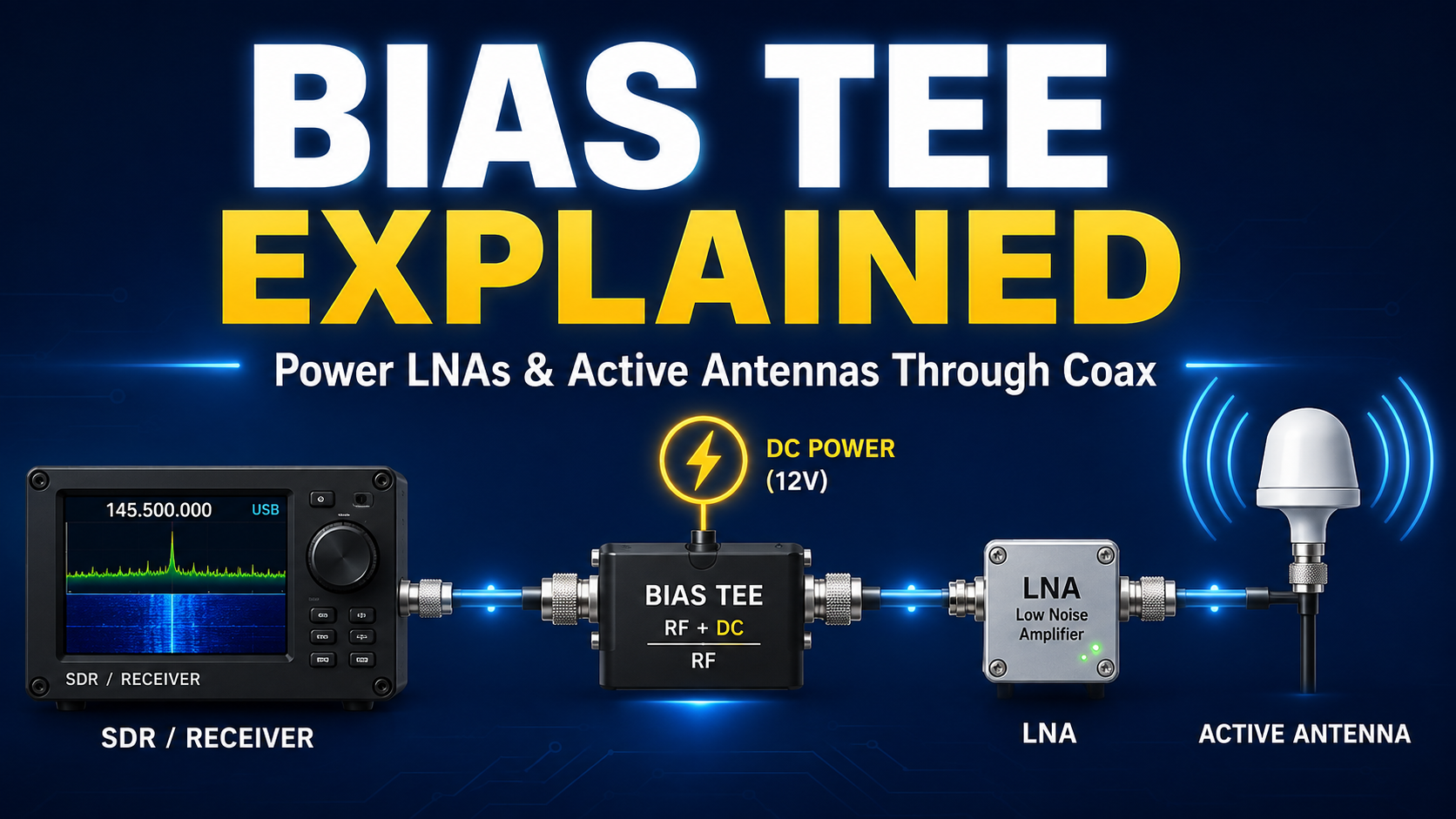
An outdoor LNA may be several meters away from your SDR receiver. An active GNSS antenna may need electrical power even though only one coaxial cable connects to it. A mast-mounted preamplifier may be positioned where running a separate DC cable would be inconvenient.
A bias tee solves this problem by allowing DC power and an RF signal to share the same coaxial cable.
Bias tees are widely used with software-defined radios, low-noise amplifiers, active antennas, GNSS receivers, satellite equipment and remote RF front ends. Some SDRs have a bias tee built into the antenna port, while other systems require an external DC injector.
The concept is simple, but using a bias tee incorrectly can damage an LNA, antenna, receiver or other RF accessory. Voltage, current capability, polarity, frequency range and whether connected components can tolerate DC all matter.
What Is a Bias Tee?
A bias tee is an RF circuit that combines or separates radio-frequency signals and DC power.
A typical receive installation looks like this:
Active antenna or LNA → coax carrying RF + DC → bias tee → SDR receiver
If the SDR already has a built-in bias tee, the arrangement can be even simpler:
Antenna → remote LNA → coax carrying RF + DC → SDR with bias tee enabled
The coax therefore performs two jobs simultaneously:
- the RF signal travels from the antenna or LNA toward the receiver;
- DC power travels in the opposite direction toward the active device.
This is sometimes described as power over coax.
Bias Tee Explained in One Table
| Part of the system | Purpose |
|---|---|
| RF port | Carries the RF signal while normally being isolated from DC |
| RF + DC port | Carries both the RF signal and DC supply voltage |
| DC port | Provides the electrical power injected onto the coax |
| Inductor / RF choke | Allows DC to reach the RF line while restricting RF from entering the power supply path |
| DC-blocking capacitor | Passes RF while preventing DC from reaching equipment that should not receive it |
How Does a Bias Tee Work?
The fundamental bias-tee circuit can be understood with only two components: an inductor and a capacitor.
The inductor passes DC
The DC supply is connected to the RF transmission line through an inductor, often called an RF choke.
At DC, an ideal inductor presents essentially no reactance. At RF frequencies, its inductive reactance rises:
XL = 2πfL
The bias tee is designed so the inductor presents a relatively high impedance to the RF signal. This helps prevent RF energy from travelling into the DC power supply.
The capacitor blocks DC
The RF path normally includes a series capacitor.
A capacitor blocks DC but presents decreasing reactance as frequency increases:
XC = 1 / (2πfC)
The capacitor is selected so it passes the intended RF frequencies with low loss while preventing the injected DC voltage from reaching the protected RF port.
RF and power share one conductor
On the RF + DC side of the bias tee, the center conductor of the coax simultaneously carries the RF waveform and a DC voltage.
The cable shield normally acts as the common return path, but the exact polarity and grounding arrangement must always be confirmed from the equipment documentation.
Why Use a Bias Tee?
The main reason is simple: it eliminates the need for a separate power cable at the antenna or remote RF device.
This is particularly useful when the active component should be installed close to the antenna.
Common applications include:
- low-noise amplifiers;
- active GNSS/GPS antennas;
- ADS-B LNAs;
- satellite receiving preamplifiers;
- L-band active antennas;
- remote VHF/UHF preamplifiers;
- mast-mounted amplifiers;
- active antenna systems;
- RF laboratory devices requiring DC bias;
- remote RF modules.
Why Put an LNA Near the Antenna?
A bias tee becomes particularly useful when powering a low-noise amplifier because an LNA is normally most effective when positioned before a long lossy coaxial cable.
Consider these two arrangements.
Preferred arrangement
Antenna → LNA → long coax → SDR
Less effective arrangement
Antenna → long coax → LNA → SDR
In the second example, cable loss has already reduced the weak antenna signal before it reaches the amplifier.
With a bias tee, the LNA can be mounted beside the antenna while receiving its electrical power through the same coax that brings the amplified RF signal indoors.
For a detailed explanation of when amplification actually improves SDR reception, read Do You Need an LNA for SDR? When It Helps and When It Makes Signals Worse.
Does a Bias Tee Amplify the RF Signal?
No.
A bias tee is not an RF amplifier.
Its purpose is to combine and separate DC and RF while disturbing the RF signal as little as practical.
The LNA or active antenna performs the amplification. The bias tee only provides the power required by that active device.
| Device | Main job |
|---|---|
| Bias tee | Add or remove DC power from an RF coaxial line |
| LNA | Amplify weak received RF signals with low added noise |
| RF filter | Pass desired frequencies and attenuate unwanted frequencies |
| DC block | Prevent DC from travelling farther along an RF path |
| Attenuator | Reduce RF signal level by a controlled amount |
Built-In Bias Tee vs External Bias Tee
There are two common ways to power an RF device through coax.
Built-in SDR bias tee
Some SDR receivers can place DC directly onto their antenna connector under software control.
The arrangement is:
SDR bias tee → coax → compatible LNA or active antenna
This is convenient because no separate DC injector is required.
External bias tee
If the receiver does not provide antenna-port power, an external bias tee can inject power into the coax.
A common arrangement is:
SDR → external bias tee → powered coax → LNA → antenna
The external bias tee normally has separate ports for:
- RF;
- RF + DC;
- DC input.
Always follow the port labels. Connecting the SDR to the wrong port may expose its RF input directly to DC.
RTL-SDR Blog V3 Bias Tee
The RTL-SDR Blog V3 provides one of the best-known examples of an SDR with integrated bias-tee power.
RTL-SDR Blog officially documents the V3 bias tee as:
- 4.5 V nominal output;
- software switchable;
- capable of supplying approximately 180 mA continuously under documented operating conditions;
- protected against accidental short circuits by its power circuitry, although prolonged shorting can still cause damage.
That makes the V3 suitable for many compatible 3–5 V receiving accessories, but it does not mean every active antenna or LNA can safely be connected.
Browse the RTL-SDR receivers and accessories category for compatible hardware.
Example: Powering the RTL-SDR Blog Wideband LNA
The Wideband LNA by RTL-SDR Blog provides a straightforward example of a bias-tee-powered accessory.
The SDRstore.eu product listing specifies:
- 50 MHz–4 GHz frequency coverage;
- less than 1 dB stated noise figure;
- 3–5 V bias-tee power requirement;
- compatibility with the RTL-SDR Blog V3's 4.5 V bias-tee supply.
A typical installation is:
Antenna → Wideband LNA → coax → RTL-SDR V3 with bias tee enabled
No additional DC cable needs to run to the LNA.
Bias Tee on bladeRF 2.0 micro
Bias-tee-powered accessories are also used on more advanced SDR platforms.
The BT-200 Bias-Tee Low Noise Amplifier is designed specifically for bladeRF receiving ports.
Nuand documents the BT-200 as drawing power directly through the bladeRF 2.0 micro's SMA RF connectors.
The bias tee can be controlled through bladeRF-cli:
set biastee rx on
and disabled with:
set biastee rx off
Nuand also warns that users should consider the SDR's total power budget when operating multiple bias-tee-powered accessories from USB power.
This illustrates an important point: a bias tee is not just about voltage. The available current and complete power budget matter too.
HackRF and Bias-Tee Power
HackRF platforms also support software-controlled antenna-port power.
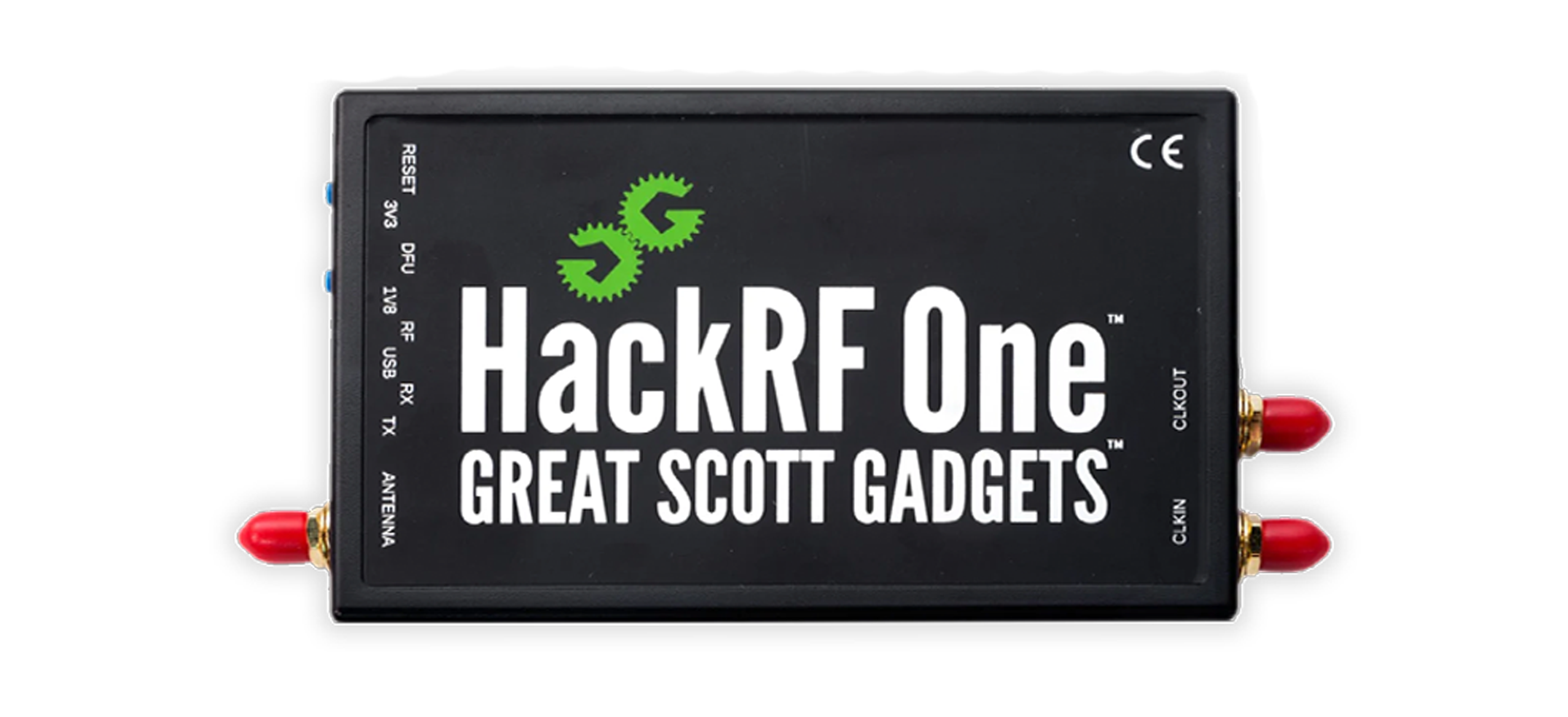
Current HackRF software includes the hackrf_biast utility for controlling bias-tee antenna power, while Great Scott Gadgets documents a built-in bias tee on HackRF Pro.
If you are using a HackRF Pro, check the documentation for your exact hardware and accessory before enabling antenna power.
Do not assume that an LNA compatible with RTL-SDR bias-tee voltage is automatically compatible with HackRF, bladeRF or another SDR.
The Most Important Bias-Tee Specifications
Before connecting anything, check all of the following.
| Specification | Why it matters |
|---|---|
| DC output voltage | The active device must tolerate and operate correctly at that voltage |
| Maximum current | The bias tee must supply enough current without exceeding its rating |
| Polarity | Incorrect polarity can damage active electronics |
| RF frequency range | The bias tee must pass the frequencies you want to receive or transmit |
| Insertion loss | Excessive loss can reduce weak-signal performance |
| Maximum RF power | Critical when the bias tee is used in a transmit-capable RF system |
| DC blocking | Determine which ports are isolated from DC and which carry RF + DC |
| Connector type | Check SMA, N-type, BNC, MCX and connector gender carefully |
| Impedance | Most SDR RF systems use 50 Ω components |
Voltage Compatibility: Never Guess
One active antenna may require 3.3 V, another 5 V and another considerably more.
Likewise, different SDRs provide different bias-tee voltages.
A device that says “bias tee compatible” is therefore not automatically compatible with every bias tee.
Before enabling power, compare:
Bias-tee output voltage ↔ accessory accepted voltage range
If the accessory requires 5 V but the SDR only supplies 3.3 V, it may fail to start or perform incorrectly.
If the accessory is rated for a lower voltage than the bias tee provides, it may be damaged.
Current Capability Matters Too
Voltage compatibility alone is not enough.
Suppose an active RF device requires 120 mA but the bias tee can safely provide only 50 mA.
Even if both operate at the same voltage, that combination is not suitable.
Possible symptoms of insufficient bias-tee current include:
- LNA failing to start;
- unstable receiver performance;
- voltage dropping under load;
- intermittent operation;
- USB instability;
- protective current limiting;
- unexpected device resets.
Always leave appropriate margin rather than designing a system that continuously operates at the absolute maximum current rating.
Voltage Drop Through Long Coaxial Cables
The DC sent through a bias tee still has to travel through real conductors with resistance.
A long or very thin coaxial cable can therefore produce a measurable voltage drop:
Vdrop = I × R
The higher the current and cable resistance, the larger the voltage lost before the active device.
For example, if a remote amplifier requires a significant amount of current and is connected through a long thin coax cable, the voltage measured at the amplifier may be lower than the voltage measured at the bias tee.
When troubleshooting long installations:
- check cable conductor resistance;
- check the current drawn by the accessory;
- measure voltage under load when safe and practical;
- use lower-resistance coax when appropriate;
- avoid unnecessary adapters and connectors.
Can You Use a Bias Tee With Any Antenna?
No.
This is one of the most important safety rules.
Some passive antennas appear as a DC short circuit between the coax center conductor and shield.
Examples can include antenna designs whose matching or feed structure provides a direct DC path.
If you enable a bias tee directly into such an antenna, the DC supply can effectively be shorted.
RTL-SDR Blog specifically warns users not to enable V3 bias-tee power into a DC-short-circuited antenna unless the powered accessory between the SDR and antenna provides the appropriate isolation.
Safe example
DC-short antenna → compatible LNA → coax → SDR bias tee
The LNA circuitry can isolate the antenna side appropriately when designed for this application.
Potentially unsafe example
DC-short antenna → coax → SDR bias tee enabled
Never assume an antenna is DC isolated. Check its specification or measure it appropriately before enabling antenna-port power.
What Is a DC Block?
A DC block is a component that prevents DC voltage from travelling farther through an RF path while allowing the RF signal to pass.
In simple terms:
RF passes — DC stops.
A DC block can be essential when one part of a system carries bias voltage but the next RF device must not receive that voltage.
Examples include protecting:
- another SDR receiver;
- a spectrum analyzer input;
- a passive splitter;
- a filter not designed for DC pass;
- measurement equipment;
- another active device with incompatible supply requirements.
Do not assume that every attenuator, splitter, filter or RF instrument already contains an appropriate DC block.
DC Pass vs DC Block Components
RF accessories may be designed very differently with respect to DC.
| Accessory description | What it normally means |
|---|---|
| DC pass | DC can travel through the specified RF path |
| DC block | DC is prevented from passing through the specified path |
| Bias tee | DC is intentionally inserted onto or extracted from the RF line |
| DC pass on one port only | Common on RF splitters where only one path carries power |
This becomes extremely important when splitters are added to active antenna systems.
Bias Tees and RF Splitters
Suppose one active antenna feeds multiple SDR receivers.
You may have:
Active antenna → coax → splitter → SDR 1 + SDR 2
If the antenna requires bias power, you cannot simply enable the bias tee on every receiver.
The splitter must have a documented DC path, and the system must be designed so multiple supplies do not drive against one another.
Depending on the splitter design:
- all ports may block DC;
- one port may pass DC;
- multiple ports may pass DC;
- the device may have a dedicated power-injection port.
Never enable multiple bias-tee supplies into a splitter unless the manufacturer explicitly documents that configuration.
Bias Tee for Active GNSS and GPS Antennas
GNSS antennas are a common example of bias-tee-powered equipment.
Many GNSS antennas contain an integrated LNA and filtering stage.
The receiver supplies DC through the coax while the antenna sends the received GNSS RF signal back down the same cable.
A typical arrangement is:
Active GNSS antenna → coax carrying GNSS RF + DC → GNSS receiver
However, active GNSS antennas vary in:
- required supply voltage;
- current consumption;
- frequency coverage;
- gain;
- filtering;
- connector type;
- polarity.
Verify the antenna datasheet before connecting it to a generic SDR bias tee.
Bias Tee for ADS-B
ADS-B reception around 1090 MHz is another common application.
An outdoor antenna may be connected to a filtered LNA mounted close to the antenna:
1090 MHz antenna → filtered LNA → long coax → SDR receiver
Bias-tee power allows the LNA to remain at the antenna without requiring a separate outdoor supply cable.
This can be particularly useful because coaxial cable attenuation becomes increasingly significant at higher frequencies.
A filtered LNA can also suppress unwanted out-of-band signals before they overload the receiver.
Bias Tee for Satellite Reception
Weak satellite signals are another natural use case for remotely powered RF amplifiers.
Applications may include:
- weather satellite reception;
- L-band satellite monitoring;
- GNSS research;
- radio astronomy experiments;
- other authorized weak-signal receiving systems.
The LNA can be mounted close to the antenna so the signal is amplified before travelling through the feedline.
The correct LNA frequency range, noise figure, gain, filtering and supply requirements still need to be matched to the project.
Does Bias-Tee Power Affect RF Performance?
A correctly designed bias tee should introduce relatively little disturbance to the intended RF signal, but no practical RF component is perfect.
Important characteristics include:
- insertion loss;
- return loss;
- frequency range;
- impedance matching;
- RF-to-DC isolation;
- DC-to-RF isolation;
- maximum voltage;
- maximum current;
- maximum RF power.
A very inexpensive bias tee advertised for an extremely wide frequency range may not provide equally good performance across that entire range.
For sensitive measurements, use manufacturer S-parameter or insertion-loss data where available.
Why Bias Tees Have Frequency Limits
The ideal description of one inductor and one capacitor is useful for understanding the concept, but real RF components have parasitic effects and self-resonant frequencies.
Mini-Circuits notes that component behavior and self resonance become important when designing practical RF and microwave bias tees.
A bias tee therefore has a specified operating frequency range.
Using it far below its minimum frequency can cause the coupling capacitor or RF choke to behave incorrectly.
Using it above its intended range can introduce:
- higher insertion loss;
- poor impedance matching;
- unexpected resonances;
- reduced RF/DC isolation.
Can a Bias Tee Be Used for Transmitting?
Some bias tees are designed for transmit systems, but you must verify the specification carefully.
Do not assume that a small receiving bias tee can safely carry transmitter power.
For transmit use, check:
- maximum RF input power;
- maximum RF voltage;
- DC voltage rating;
- DC current rating;
- frequency range;
- connector power handling;
- load VSWR requirements;
- whether connected active devices are receive-only.
A receive-only LNA can be destroyed by transmitter power.
How to Connect an External Bias Tee
Port labels differ between manufacturers, but a typical bias tee has three connections:
- RF: connect toward the receiver or other DC-sensitive RF equipment.
- RF + DC: connect toward the powered LNA or active antenna.
- DC: connect the specified power supply.
A typical receive system is:
SDR → RF port of bias tee → RF + DC port → coax → powered LNA → antenna
Before applying power:
- verify the bias tee frequency range;
- verify the LNA voltage requirement;
- verify current consumption;
- verify polarity;
- confirm which port carries DC;
- confirm the SDR side is DC blocked;
- inspect all connectors;
- apply power only after the RF chain is confirmed.
Should You Use One Bias Tee or Two?
For many SDR installations, only one bias tee is required.
If an LNA is specifically designed to receive its power through the RF connector, the active device already contains the circuitry necessary to extract that power.
You normally need:
One DC injector at the receiver end → coax → bias-powered LNA
A second bias tee may be required when you need to deliberately extract DC at the remote end for equipment that does not have integrated bias-power extraction.
Do not add a second bias tee automatically. Follow the design of the powered accessory.
How to Check If an LNA Supports Bias-Tee Power
Look for wording such as:
- bias-tee powered;
- phantom powered;
- power over coax;
- DC through RF connector;
- DC feed through SMA;
- active antenna supply;
- RF + DC input.
Then verify the actual voltage and current requirements.
An LNA with a separate USB connector or separate VCC pins may not automatically accept DC through its RF input.
Can You Measure Bias-Tee Voltage With a Multimeter?
For basic troubleshooting, DC voltage can often be checked with suitable test equipment, but use caution around RF connectors.
Before measuring:
- disconnect sensitive RF accessories;
- confirm the expected voltage;
- avoid shorting the SMA center contact to the outer conductor;
- use appropriate probes or an RF test adapter;
- disable transmitter functionality;
- follow the manufacturer's test procedure where available.
A momentary probe slip across an SMA connector can short the bias-tee output.
Common Bias-Tee Mistakes
1. Enabling power without checking the antenna
A DC-short antenna can short the bias supply.
2. Assuming all bias tees output 5 V
They do not. Voltage depends on the device.
3. Ignoring current consumption
A compatible voltage with insufficient available current can still result in an unreliable system.
4. Connecting the SDR to the RF + DC port
With an external bias tee, this may expose an SDR input to unwanted DC if the system is connected incorrectly.
5. Enabling two bias tees at once
This can happen when multiple receivers are connected through a splitter. Two independent power supplies should not be combined unless the complete RF network is specifically designed for it.
6. Using a non-DC-pass splitter
The RF signal may pass while the remote LNA receives no power.
7. Using a DC-pass component unintentionally
DC may reach equipment that was expected to be isolated.
8. Forgetting voltage drop
Long, thin cables and high current draw can reduce the voltage available at the remote device.
9. Leaving bias power enabled while changing accessories
Hot-plugging RF accessories with DC present increases the risk of accidental shorts.
10. Using a receive-only bias tee in a transmit chain
RF power ratings must be checked before transmitting through the component.
Bias Tee Troubleshooting
The LNA does not turn on
Check:
- whether bias-tee power is enabled in software;
- output voltage;
- available current;
- cable continuity;
- whether any splitter passes DC;
- whether the LNA actually supports power through coax;
- connector orientation;
- voltage at the remote end.
Reception becomes worse when the LNA turns on
The bias tee itself may be working correctly.
The LNA could instead be overloading the SDR or amplifying powerful unwanted signals.
Try:
- reducing SDR gain;
- adding appropriate RF filtering;
- testing without the LNA;
- checking whether the LNA gain is excessive;
- checking for nearby FM, cellular or other strong transmitters.
Read Do You Need an LNA for SDR? for a complete explanation of LNA overload.
The bias tee keeps shutting down
Possible causes include:
- short circuit;
- excessive current draw;
- incorrectly wired RF accessory;
- damaged coax;
- DC-short antenna;
- insufficient USB power;
- thermal or over-current protection activating.
RF works with bias power off but disappears when enabled
Check for:
- receiver overload;
- faulty active device;
- wrong supply voltage;
- incorrect bias-tee orientation;
- poor power supply filtering;
- active device oscillation;
- excessive gain.
Bias Tee Buying Checklist
Before purchasing a bias tee or bias-powered accessory, answer these questions:
- What frequencies must it pass?
- What voltage does the active device require?
- How much current does it draw?
- Can the bias source provide that current continuously?
- What polarity does the device expect?
- Is the system 50 Ω or 75 Ω?
- What connectors are required?
- Does the RF path need to support transmission?
- What maximum RF power must it handle?
- Do filters or splitters in the path pass DC?
- Is a DC block required before another receiver or instrument?
- How much insertion loss is acceptable?
Recommended SDRstore.eu Equipment
| Equipment | Bias-tee relevance |
|---|---|
| RTL-SDR Blog V3 | Integrated software-controlled 4.5 V bias tee for compatible active RF accessories |
| RTL-SDR Blog Wideband LNA | Requires 3–5 V bias-tee power and is compatible with RTL-SDR Blog V3 power |
| BT-200 bladeRF LNA | Designed to draw power from compatible bladeRF RX ports |
| HackRF Pro | Includes software-controlled antenna-port bias power for compatible accessories |
| RTL-SDR category | Receivers, LNAs and related SDR accessories |
Safety Rules Before Enabling a Bias Tee
- Confirm the required voltage.
- Confirm maximum available and required current.
- Confirm polarity.
- Check whether the antenna presents a DC short.
- Check every splitter, filter and adapter for DC-pass behavior.
- Do not expose test equipment to DC unless its input permits it.
- Disable bias power before reconnecting RF accessories where practical.
- Do not transmit through receive-only LNAs or bias tees.
- Do not assume connector compatibility means electrical compatibility.
- Use the manufacturer's documentation rather than relying on a generic bias-tee voltage.
Official Technical References
- Mini-Circuits — RF/Microwave Bias Tees from Theory to Practice
- RTL-SDR Blog — V3 Dongle User Guide
- RTL-SDR Blog — Wideband Bias-Tee Powered LNA
- Nuand — BT-200 Bias-Tee Low Noise Amplifier
- Great Scott Gadgets — HackRF Software Releases
Final Recommendation
A bias tee is one of the simplest ways to improve the practicality of a remote RF receiving system.
It lets an SDR or external DC injector power a compatible LNA or active antenna through the same coaxial cable that carries the RF signal.
For a typical weak-signal SDR installation, this means you can place the LNA where it is most useful:
Antenna → LNA → coax carrying RF + DC → SDR
But never enable bias power blindly.
Check the voltage, current requirement, polarity, RF frequency range, antenna DC behavior, splitter DC-pass configuration and maximum RF power first.
The important question is not simply whether both products say “bias tee.” The important question is whether the entire RF and DC path is electrically compatible.
FAQ
What is a bias tee?
A bias tee is an RF circuit that combines DC power and an RF signal onto the same transmission line. It is commonly used to power LNAs and active antennas remotely through coaxial cable.
Why is it called a bias tee?
The name comes from the circuit's tee-like function: an RF path and a DC bias path are combined into one RF + DC connection.
Does a bias tee amplify RF signals?
No. A bias tee only combines or separates RF and DC. An LNA or other active RF device provides amplification.
Can I use a bias tee with any LNA?
No. The LNA must support power through its RF connector and its voltage, current and polarity requirements must match the bias-tee supply.
Can I enable a bias tee with any antenna?
No. Some antennas present a DC short between the center conductor and shield. Enabling bias power directly into such an antenna can short the bias-tee supply.
What voltage does the RTL-SDR Blog V3 bias tee provide?
RTL-SDR Blog officially documents the V3 as providing a software-controlled nominal 4.5 V bias tee with approximately 180 mA continuous current capability under documented operating conditions.
Can RTL-SDR V3 power an LNA?
Yes, when the LNA accepts the V3's bias-tee voltage and current capability. The RTL-SDR Blog Wideband LNA, for example, requires 3–5 V bias power and is documented as compatible with the V3.
Why should an LNA be placed close to the antenna?
Placing the LNA before a long coaxial cable allows weak received signals to be amplified before cable loss reduces them. Bias-tee power makes this possible without running a second power cable.
What is a DC block?
A DC block allows the RF signal to pass while preventing DC voltage from continuing along the RF path. It is useful for protecting equipment that should not receive bias voltage.
Do I need two bias tees?
Usually not when an active antenna or LNA is specifically designed for bias-tee power. One bias tee injects power at the receiver end, and the active device extracts its required power internally. Some custom systems may require a second circuit to extract DC remotely.
Can I put a splitter between a bias tee and active antenna?
Only if the splitter's DC-pass behavior is compatible with the design. Some splitters block DC, while others pass DC through one or more ports. Do not combine multiple active bias supplies unless the system is specifically designed for it.
Can a bias tee be used for transmitting?
Only when the bias tee is explicitly rated for the required transmitter frequency and RF power. A receiving bias tee or receive-only LNA should never be assumed to tolerate transmitter power.
Why does my LNA not work through a long coax cable?
Possible causes include cable voltage drop, insufficient bias-tee current, a splitter or filter that blocks DC, incorrect voltage, incorrect polarity or a cable fault. Measure and verify the complete RF and DC path.
No posts found
Write a review






We support all major card and digital payment options. More local methods are available and shown during checkout.
You enter into a binding sales contract once you have received an 'order confirmation and sales receipt' email from us, in line with our Sales & Delivery conditions. Therefore, sdrstore.eu has the right to cancel your order in the event of technical problems, delivery failure, Fair use policy and other similar situations.





Your payments are protected by advanced encryption and 3-D Secure authentication for safe online shopping.