





Solar Meshtastic with LILYGO: Battery and Panel Sizing for European Winter
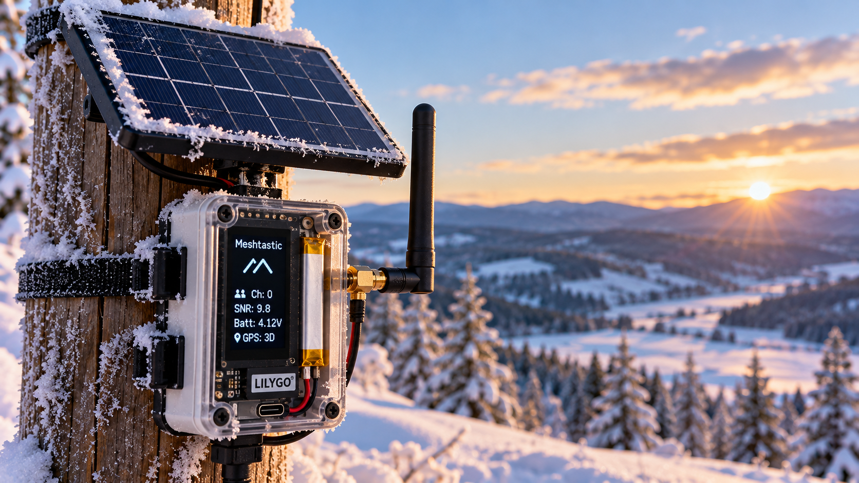
Size a solar Meshtastic node from its measured daily energy use, the darkest useful month at its installation site and the number of sunless days it must survive. For a LILYGO T-Beam build, a battery that works overnight on a desk can be far too small for a shaded European winter installation.
Start with the exact board and frequency option. Our T-Beam Supreme listing offers different radio-band and GNSS configurations. Use the hardware appropriate to your local mesh and select the corresponding Meshtastic region. A solar supply does not change the radio's permitted operating conditions.
Measure the complete node before buying the panel
Measure energy over at least a representative day with the intended firmware, antenna, message activity and peripherals. Include the controller's own consumption and any voltage conversion. A USB meter measures the USB supply path; a battery-side logger measures a different boundary. State which boundary you use and avoid counting conversion losses twice.
For a stationary node, investigate disabling unnecessary GNSS updates, Wi-Fi and display activity. Then measure again. Do not copy a low-current figure from another ESP32 board or a different firmware role. Meshtastic's device documentation describes role-specific sleep behaviour; a tracker sleeping between position reports is not equivalent to an available relay.
Convert the load into watt-hours
Use daily energy = average power × 24 hours. If your complete regulated load averages an assumed 0.25 W, it needs 6 Wh/day. At an assumed 0.50 W, it needs 12 Wh/day. These are sizing examples, not measured T-Beam consumption.
| Assumed average load | Daily energy | Energy for three sunless days |
|---|---|---|
| 0.25 W | 6 Wh | 18 Wh usable |
| 0.50 W | 12 Wh | 36 Wh usable |
| 1.00 W | 24 Wh | 72 Wh usable |
Use watt-hours when comparing batteries at different voltages. A 3 Ah cell at 3.7 V nominal contains a nominal 11.1 Wh. That is not 11.1 Wh guaranteed at the node after cold-weather capacity reduction, cutoff, ageing and regulator losses.
Choose battery reserve separately from panel output
For a first calculation, battery nominal energy = daily load × autonomy days ÷ usable-energy fraction. If the 6 Wh/day example needs three days and you assume 70% of nominal energy reaches the load under your design conditions, the result is 25.7 Wh. At 3.7 V nominal, that is approximately 6.95 Ah.
The assumed 70% combines your chosen reserve and losses; replace it with justified values for the actual pack. Do not treat it as a battery specification. A larger professionally assembled pack and appropriate external power system may be more practical than the board's single-cell holder. Do not improvise a parallel pack from loose, unmatched cells.
Meshtastic's T-Beam hardware notes specify an original-length, unprotected flat-top 18650 for the applicable holders. That mechanical requirement does not establish that every 18650 chemistry, charging current or external pack is suitable.
Use local winter sunlight, then allow recovery time
Use the European Commission's PVGIS off-grid tool with the actual location, panel slope, orientation, battery energy and daily consumption. Examine winter energy deficits and battery-empty behaviour. Nearby trees, roof edges and snow can make the real installation worse than a terrain-based model.
A simple screening equation is panel watts = daily load ÷ equivalent full-sun hours ÷ net charging efficiency. With an assumed one equivalent full-sun hour and 60% net efficiency, 6 Wh/day requires 10 W just to replace a typical day's consumption. Neither assumption represents all of Europe.
Recovery needs additional energy. After three sunless days, the example has an 18 Wh deficit. Replacing that over two useful days while also running the node needs 6 + 18/2 = 15 Wh/day. Under the same assumptions, that means 25 W of panel capacity. Repeat the calculation for a poorer solar window before choosing a panel.
Specify a proper solar power path
- A panel with voltage and cold open-circuit voltage within the controller's limits.
- A controller matched to the battery chemistry, series-cell count and permitted charge current.
- Battery-temperature sensing and charging inhibition outside the cell manufacturer's limits.
- A regulated output appropriate to the board's chosen input, with verified polarity.
- Low-voltage disconnect, suitable fusing, cable strain relief and weather-resistant housing.
Do not connect a raw solar panel directly to USB or the battery holder. An onboard charging chip does not establish a complete solar controller, cold-charge protection or stable operation under changing illumination.
Cold charging is a separate problem from cold discharge. Follow the selected cell's temperature specification and verify that the assembled controller actually enforces it. TI's charging application note explains why charge current and voltage need temperature-dependent control. A sealed box and insulation alone do not guarantee a warm battery.
Commission the node before mounting it remotely
- Record firmware target, settings and a full-day energy measurement.
- Disconnect solar input and confirm the intended autonomy without over-discharging the pack.
- Verify cold-charge inhibition using the controller manufacturer's approved test procedure.
- Restore input and check that the node recovers automatically after low-voltage shutdown.
- Check message exchange, enclosure condensation and charging noise with the final wiring.
Frequently asked questions
Is a 10 W panel enough?
Only if the measured load, local winter yield and recovery requirement support it. In the example above, 10 W covers normal consumption but does not provide the calculated two-day recovery margin.
Can I leave GNSS enabled?
Yes, if your application needs it and the measured energy budget includes it. A fixed node may benefit from a configured fixed position instead.
Will a larger battery fix winter shading?
It extends reserve time. It cannot fix a persistent energy deficit when the panel produces less than the node consumes.
Should I use T-Beam Supreme or classic T-Beam?
Compare the exact hardware in our T-Beam buying guide, then measure the chosen configuration. Processor and radio names alone cannot predict whole-node autonomy.
Choose your LILYGO variant first, then use our online quote process to request matching boards and identify the power-system parts you need confirmed. This design example is not a preconfigured solar kit.
Shop products for this guide
Explore relevant products from our store.
Alternatives considered
Other relevant options for this guide.
-
LILYGO Meshtastic T-Beam V1.2 ESP32 LoRa 915MHz 433MHz 868MHz 923MHz WiFi BLE GPS With 0.96 inch OLED
Le T-Beam V1.2 est l’autre génération T-Beam du catalogue, avec ESP32 et SX1276/SX1278. Je préfère le Supreme, qui est décrit avec ESP32-S3 et SX1262 ; le V1.2 se justifie surtout si vous avez une contrainte de compatibilité précise avec ce modèle.
No posts found
Write a review






We support all major card and digital payment options. More local methods are available and shown during checkout.
You enter into a binding sales contract once you have received an 'order confirmation and sales receipt' email from us, in line with our Sales & Delivery conditions. Therefore, sdrstore.eu has the right to cancel your order in the event of technical problems, delivery failure, Fair use policy and other similar situations.






Your payments are protected by advanced encryption and 3-D Secure authentication for safe online shopping.