





50 Ohm vs 75 Ohm: Why RF Systems Use Different Impedances
Why do SDRs, antennas, RF amplifiers and laboratory instruments usually use 50 ohms, while television, CATV and professional video systems often use 75 ohms?
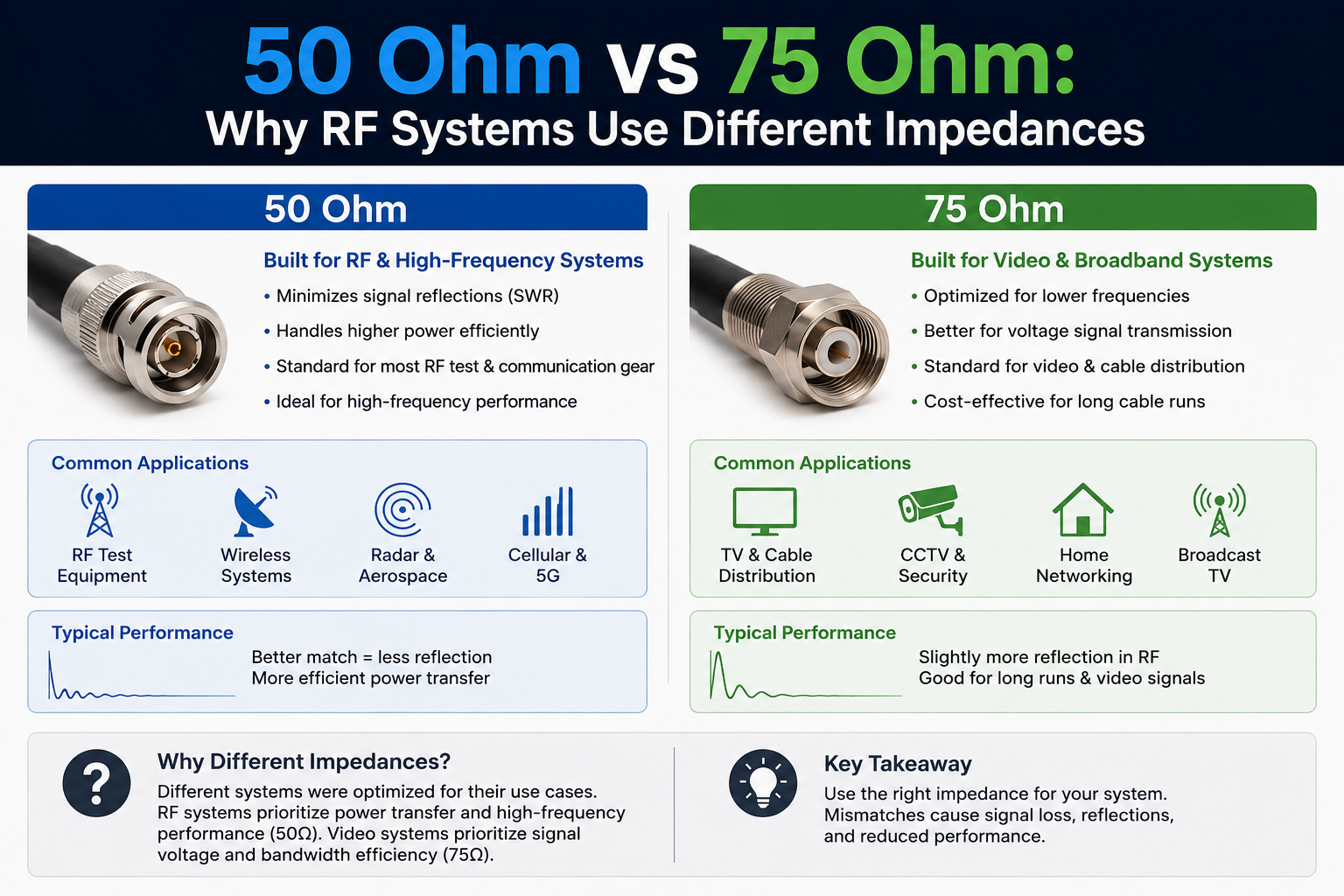
The answer is not that one impedance is universally better. 50 Ω and 75 Ω were optimized around different engineering priorities, and both became established standards with their own cables, connectors, antennas and measurement equipment.
For most SDR, amateur radio, cellular, Wi-Fi, RF laboratory and microwave applications, 50 Ω is the normal reference impedance. For television distribution, satellite TV, CATV and many broadcast-video systems, 75 Ω is the normal choice.
The important rule is simple: once a system is designed around one impedance, keep the transmission line, connectors, antennas, filters and test equipment matched to that impedance whenever practical.
50 Ohm vs 75 Ohm: Quick Answer
| Characteristic | 50 Ω | 75 Ω |
|---|---|---|
| Typical applications | SDR, radio, wireless, cellular, Wi-Fi, GPS/GNSS RF chains, microwave, RF test equipment | TV, CATV, satellite television, broadcast video, SDI and broadband distribution |
| Main engineering priority | Practical balance between power handling and transmission loss | Low-loss signal distribution where high RF power is less important |
| Common RF connectors | SMA, N-type, many BNC systems, TNC and laboratory interfaces | F-type, 75 Ω BNC and broadcast-oriented interfaces |
| Common coax examples | RG-58, RG-174, RG-316 and many RF/microwave cable assemblies | RG-6, RG-59 and RG-11 variants commonly used for video/CATV |
| Typical SDR compatibility | Yes — most SDR RF ports are designed around 50 Ω | Usually requires appropriate matching when connecting to a 50 Ω SDR |
| Typical VNA reference | Very common | Available on specialized instruments or through appropriate conversion methods |
These are typical examples rather than a substitute for checking a specific product datasheet. Connector families and coax names can have multiple variants.
What Does 50 Ohm or 75 Ohm Actually Mean?
The impedance printed on an RF cable is its characteristic impedance. It is not simply the DC resistance you would measure from one end of the center conductor to the other with a multimeter.
An RF transmission line behaves as a distributed electromagnetic structure. Its geometry, conductor dimensions and dielectric material determine how voltage and current waves propagate along it.
For an ideal low-loss coaxial transmission line, characteristic impedance is approximately:
Z0 ≈ (60 / √εr) × ln(D/d)
- D is the inside diameter of the outer conductor.
- d is the outside diameter of the center conductor.
- εr is the relative permittivity of the dielectric.
This is why changing the dimensions or dielectric inside a coaxial cable changes its characteristic impedance.
It also explains why crushing coax, using unsuitable connectors or making poor transitions can create impedance discontinuities even when the cable was originally manufactured correctly.
Why Do RF Systems Use 50 Ohms?
The traditional explanation comes from coaxial transmission-line engineering.
For ideal air-dielectric coax, two useful operating points occur at different impedances:
- Around 30 Ω, coax can achieve very high power-handling capability.
- Around 77 Ω, conductor-related attenuation can reach a minimum.
Neither extreme is ideal for every RF application.
A 30 Ω system would favor power handling but sacrifice more efficiency. A roughly 77 Ω system would favor low attenuation but would not provide the same power-handling characteristics.
50 Ω became an effective engineering compromise between those requirements.
That choice then became deeply established throughout RF engineering. Today, a huge ecosystem of transmitters, receivers, SDRs, antennas, amplifiers, filters, attenuators, directional couplers, signal generators, spectrum analyzers and VNAs is designed around 50 Ω.
Where 50 ohms is normally used
- Software-defined radios
- Amateur radio equipment
- RF and microwave laboratory instruments
- Signal generators
- Spectrum analyzers
- Vector network analyzers
- RF amplifiers and LNAs
- Cellular infrastructure
- Wi-Fi RF hardware
- GNSS RF chains
- LoRa and other wireless modules
- RF filters and attenuators
- Many antenna systems
If you are building an SDR or general RF bench, 50 Ω should normally be your default assumption until the documentation says otherwise.
You can browse SDR instruments and RF test and measurement equipment at SDRstore.eu.
Why Do TV and Video Systems Use 75 Ohms?
75 Ω systems developed around a different requirement: efficiently moving relatively low-power broadband signals through coaxial distribution networks.
This makes 75 Ω well suited to applications such as:
- Cable television
- Terrestrial television distribution
- Satellite television
- Broadcast infrastructure
- SDI video
- Video distribution systems
- Broadband coax networks
These systems generally do not need to send the same transmitter power through the cable as an RF transmitter feeding an antenna. Attenuation and signal integrity across long distribution networks become more important priorities.
That is one reason 75 Ω became established throughout broadcast and video infrastructure while 50 Ω became dominant in RF communications and test equipment.
Is 75 Ohm Coax Better Than 50 Ohm Coax?
Not universally.
Saying that 75 Ω cable is simply “better” because it can offer favorable attenuation characteristics ignores the rest of the system.
A high-quality 75 Ω cable connected between 50 Ω components introduces an impedance mismatch. Likewise, an excellent 50 Ω RF cable is not the correct choice for a precision 75 Ω broadcast chain if the rest of that system expects 75 Ω.
The better cable is normally the cable designed for the impedance, frequency, attenuation, power and connector requirements of the complete system.
What Happens If You Connect 50 Ohms to 75 Ohms?
When an RF wave reaches a sudden change in impedance, part of its energy can be reflected toward the source instead of continuing toward the load.
For a simple ideal transition from 50 Ω to 75 Ω:
Γ = (75 − 50) / (75 + 50) = 0.2
This gives approximately:
| Mismatch measurement | Ideal 50 Ω to 75 Ω transition |
|---|---|
| Reflection coefficient magnitude | 0.20 |
| Reflected power | 4% |
| Return loss | 13.98 dB |
| VSWR | 1.5:1 |
| Single-interface mismatch loss | Approximately 0.18 dB |
At first glance, 0.18 dB may not look severe. That is why a mismatched system can sometimes appear to work.
However, a real installation may contain multiple transitions, connectors, adapters, filters, splitters and cable sections. Reflections also have phase, so the resulting frequency response can contain peaks and dips rather than behaving like one fixed 0.18 dB attenuator.
This becomes particularly important when:
- frequency increases;
- cables become electrically longer;
- measurement accuracy matters;
- transmitter power increases;
- several mismatches are cascaded;
- wide bandwidth is required;
- filters or matching networks are involved.
For more background on reflections, read SWR vs Impedance vs Return Loss: Antenna Measurements Explained.
Can You Use 75 Ohm Cable With an SDR?
Sometimes it will work, especially for receive-only experiments, but that does not make it a properly matched RF system.
Most SDR hardware uses 50 Ω RF interfaces. For example, the wider SDR and RF laboratory ecosystem around SMA-connected receivers, transmitters, filters and amplifiers is normally based on 50 Ω.
Browse the RTL-SDR receiver and accessory range for examples of SDR equipment using RF-oriented SMA connections.
Receive-only SDR
If you connect a 75 Ω television antenna and RG-6 feedline to a 50 Ω receiver, you may still receive strong signals perfectly well. For many casual receive-only projects, the resulting mismatch may be less important than:
- antenna location;
- feedline attenuation;
- local interference;
- receiver sensitivity;
- noise figure;
- antenna gain.
That does not mean the mismatch has disappeared. It only means the complete link budget may still be good enough.
Transmitting or laboratory measurements
For transmitters, filters, amplifiers, calibrated measurements or repeatable laboratory work, impedance should be treated much more carefully.
Do not assume that a random physical adapter converts 75 Ω to 50 Ω. A connector adapter may only change the connector shape while preserving—or disturbing—the electrical impedance.
If a true conversion is required, use a properly specified 50-to-75 Ω impedance matching transformer or minimum-loss matching pad suitable for the frequency range and power level.
A Connector Adapter Is Not Necessarily an Impedance Adapter
This is one of the easiest RF mistakes to make.
For example, you can buy adapters that mechanically connect BNC, SMA, N-type or F-type interfaces. That does not automatically mean they transform one characteristic impedance into another.
A simple metal adapter normally provides only a physical interface conversion.
A true impedance converter requires an RF network designed to transform the impedance.
| Device | What it does |
|---|---|
| BNC-to-SMA mechanical adapter | Changes connector format; normally does not transform 50 Ω into 75 Ω |
| 50-to-75 Ω minimum-loss pad | Provides controlled impedance conversion, usually with intentional insertion loss |
| Impedance transformer | Transforms one impedance to another using an appropriate RF network |
| 75 Ω terminator | Correctly terminates a 75 Ω transmission line |
| 50 Ω terminator | Correctly terminates a 50 Ω transmission line |
50 Ohm BNC vs 75 Ohm BNC
BNC is particularly important because BNC connectors are manufactured in both 50 Ω and 75 Ω versions.
They can look extremely similar, and some versions can physically mate. That does not mean mixing them is good RF practice.
Amphenol RF specifically advises matching the connector impedance to the system because mixing 50 Ω and 75 Ω versions creates an impedance discontinuity that can increase reflections, increase VSWR and reduce signal integrity.
Do not identify impedance only by looking at the outside of a connector. Check:
- the equipment datasheet;
- connector part number;
- manufacturer documentation;
- cable markings;
- system specification.
Common 50 Ohm and 75 Ohm Coax Cables
| Cable family | Typical impedance | Common use |
|---|---|---|
| RG-58 | 50 Ω | General RF and radio |
| RG-174 | 50 Ω | Compact RF connections and internal cabling |
| RG-316 | 50 Ω | Short RF jumpers and laboratory assemblies |
| RG-6 | 75 Ω | CATV, television and satellite distribution |
| RG-59 | 75 Ω | Video and legacy broadcast applications |
| RG-11 | 75 Ω | Longer CATV distribution runs |
These are common examples. Always verify the exact manufacturer specification because cable families, specialized variants and similarly named products can differ.
50 Ohm vs 75 Ohm for SDR Projects
| Project | Normally choose | Reason |
|---|---|---|
| RTL-SDR antenna system | 50 Ω | Matches the normal SDR/RF accessory ecosystem |
| HackRF or general-purpose SDR | 50 Ω | RF transceiver ecosystem is normally 50 Ω |
| USRP research setup | 50 Ω | RF laboratory and microwave equipment is generally 50 Ω |
| LoRa development | 50 Ω | Modules, antennas and RF test accessories typically use 50 Ω |
| ADS-B SDR station | 50 Ω | Typical SDR, LNA, filter and antenna chains are designed around 50 Ω |
| CATV distribution | 75 Ω | Designed around the 75 Ω cable-TV ecosystem |
| Satellite television | 75 Ω | Standard satellite-TV feed and distribution architecture |
| SDI video installation | 75 Ω | Broadcast video interfaces use a 75 Ω signal path |
Does Cable Length Change Its Characteristic Impedance?
No. A correctly manufactured 50 Ω cable does not become 75 Ω because it is longer, and a 75 Ω cable does not become 50 Ω because it is shorter.
Length changes other things, including:
- total attenuation;
- signal delay;
- electrical phase length;
- how reflected signals combine;
- the effect of a mismatch at different frequencies.
The cable's nominal characteristic impedance is primarily determined by its physical geometry and dielectric structure.
If you want to measure actual feedline attenuation, see How to Test Coax Cable Loss with a NanoVNA.
How Important Is the Mismatch at Low Frequencies?
A transmission-line mismatch becomes most obvious when the cable is electrically significant compared with the wavelength of the signal.
At low frequencies and with very short interconnects, the effect may be small enough that a system still operates acceptably.
As frequency or cable length increases, transmission-line behavior becomes increasingly important.
This is why a poor adapter that appears harmless in a low-frequency experiment can become a serious problem at hundreds of megahertz or several gigahertz.
Can a NanoVNA Measure 75 Ohm Systems?
You need to understand what impedance the instrument itself uses.
Many affordable VNAs and RF instruments are fundamentally designed around a 50 Ω system impedance. Their calibration standards, ports and normal Smith Chart reference are therefore based around 50 Ω.
For example, SDRstore.eu's NanoVNA-H4 includes a calibration load used as the 50 Ω reference for normal RF measurements.
Read the NanoVNA Setup Guide for calibration, SWR, impedance and Smith Chart fundamentals.
Changing the displayed reference is not the same as changing the hardware
Some professional network analyzers can display measurements normalized to a different system impedance. However, changing a software reference alone does not physically transform a 50 Ω instrument port into a 75 Ω port.
Professional workflows may use:
- a native 75 Ω VNA;
- precision 50-to-75 Ω minimum-loss pads;
- appropriate calibration standards;
- fixture de-embedding or renormalization;
- a manufacturer-documented conversion workflow.
Keysight, for example, documents measurement workflows in which 50-to-75 Ω minimum-loss pads are used and measurement results are then reported relative to the required system impedance.
For general 50 Ω RF work, SDRstore.eu also offers higher-range tools including the NanoVNA-F V3 and LibreVNA.
If you are deciding between antenna/network analysis and spectrum analysis, read NanoVNA vs TinySA: Which RF Tool Do You Actually Need?.
How to Check Whether Your Equipment Is 50 or 75 Ohms
- Read the product datasheet. This is the most reliable method.
- Check the port labeling. Instruments sometimes print 50 Ω or 75 Ω next to the input.
- Check the coax markings. Cable type and manufacturer specifications normally identify impedance.
- Check the connector part number. This is particularly important with BNC because both impedances exist.
- Check the calibration standards. A VNA calibration kit should match the measurement system.
- Do not assume impedance from connector shape alone.
When Does 50 vs 75 Ohm Matching Matter Most?
1. Transmitting RF power
Use the impedance specified by the transmitter, amplifier, cable and antenna system. Significant mismatch can increase reflected power and stress the transmitter or cause protection circuits to reduce output.
2. Precision RF measurements
Laboratory measurements require controlled reference impedances. Mixing 50 and 75 Ω hardware without accounting for it can invalidate return-loss, insertion-loss and gain results.
3. Filters and amplifiers
RF filters and amplifiers are characterized for specific source and load impedances. Their published response assumes the specified termination.
4. Long cable runs
Long RF transmission lines make attenuation, reflections and impedance control increasingly important.
5. Wideband systems
A mismatched adapter or connector can create a frequency-dependent response. Wideband SDR and RF systems therefore benefit from maintaining controlled impedance throughout the signal path.
Which Impedance Should You Buy?
For most SDRstore.eu customers, the practical decision is straightforward.
Choose 50 ohms if you are building:
- an SDR station;
- an amateur-radio setup;
- an RF laboratory;
- a spectrum-monitoring system;
- a wireless development bench;
- a LoRa or IoT RF test setup;
- an antenna measurement setup;
- a GNU Radio research system;
- a cellular or microwave experiment.
Choose 75 ohms if you are building:
- a CATV system;
- a television distribution network;
- a satellite-TV installation;
- a professional SDI/video signal chain;
- equipment specifically documented for 75 Ω operation.
If you need to connect both systems
Do not solve the problem with a random mechanical adapter.
Identify:
- source impedance;
- load impedance;
- frequency range;
- maximum power;
- required insertion loss;
- connector types;
- measurement accuracy requirement.
Then select a properly specified impedance transformer or 50-to-75 Ω matching pad.
Recommended RF Measurement Tools
If you are troubleshooting impedance, antennas, connectors or coax, a vector network analyzer is one of the most useful tools to own.
- NanoVNA-H4 — practical handheld option for antenna impedance, SWR, return loss and cable testing.
- NanoVNA-F V3 — higher-frequency portable VNA option.
- LibreVNA — USB full two-port VNA for more advanced RF bench work.
- RF Test & Measurement — browse VNAs, spectrum analyzers, signal generators, RF power meters and related equipment.
For Universities, RF Labs and Engineering Teams
Universities, research laboratories, telecom companies, RF engineering teams and other businesses can request formal quotations directly through SDRstore.eu.
Open the required product and use the Add to Quote option on the product page. When browsing product listings, you can also use the document icon on a product card to add equipment to your quote request.
This is useful when preparing multi-item RF benches containing SDRs, VNAs, spectrum analyzers, antennas and other measurement equipment.
Safety Notes
- Do not connect a transmitter directly to a VNA, SDR or spectrum analyzer unless its input is designed for the applied power.
- Use suitable attenuators, directional couplers or dummy loads for conducted transmitter testing.
- Check whether active antennas or LNAs place DC bias voltage on the coax before connecting test equipment.
- Discharge outdoor antenna feedlines safely before connecting sensitive instruments.
- Use the correct power rating for terminators and impedance-matching devices.
- Do not assume that physical connector compatibility means electrical compatibility.
Technical References
- Amphenol RF — Difference Between 50 Ohm and 75 Ohm Connectors
- Amphenol RF — Using 50 Ohm Connectors in a 75 Ohm System
- Shure — Transmission Lines and Standard RF Impedance
- Cadence — Conquer Radio Frequency: Why 50 Ω?
Final Recommendation
Use 50 Ω for SDR, radio, wireless and RF laboratory systems unless the equipment manufacturer specifies otherwise. Use 75 Ω for television, CATV, satellite-TV and broadcast-video systems designed around 75 Ω.
The difference is not simply a cable preference. Characteristic impedance is part of the electrical design of the complete signal path.
A short 50-to-75 Ω mismatch may appear to work, particularly in a receive-only system, but precision RF work should maintain the correct impedance or use a properly designed impedance converter.
If you are diagnosing an RF system, measure rather than guess: check the documentation, verify the cable and connector impedance, calibrate your VNA correctly and inspect SWR, return loss and impedance at the frequencies that actually matter.
FAQ
Why is RF usually 50 ohms?
50 Ω became the dominant RF standard because it provides a practical balance between low transmission loss and RF power-handling capability in coaxial systems. The surrounding RF equipment ecosystem was subsequently standardized around it.
Why is television coax 75 ohms?
75 Ω is widely used for television, CATV, satellite TV and broadcast video because these applications prioritize efficient low-power broadband signal distribution rather than high transmitter power handling.
Can I connect 75 ohm coax to a 50 ohm SDR?
It can work for receive-only applications, but it creates an impedance mismatch. For precision measurements, wideband systems or transmit applications, use a properly matched 50 Ω system or an appropriate impedance-conversion device.
How much signal is reflected between 50 and 75 ohms?
An ideal 50-to-75 Ω discontinuity has a reflection coefficient magnitude of 0.2, corresponding to approximately 4% reflected power and a VSWR of 1.5:1.
Is 75 ohm coax lower loss than 50 ohm coax?
75 Ω is closer to the classical minimum-loss impedance for ideal air-dielectric coax, but real cable attenuation also depends on cable diameter, conductors, dielectric, shielding and frequency. Compare actual manufacturer attenuation specifications rather than impedance alone.
Is RG-6 50 or 75 ohms?
RG-6 used for television, CATV and satellite distribution is normally a 75 Ω cable. Check the exact manufacturer datasheet before using a specific cable.
Is RG-58 50 or 75 ohms?
RG-58 is normally associated with 50 Ω RF systems and is commonly used for radio and general-purpose RF connections.
Are all BNC connectors 50 ohms?
No. BNC connectors are available in both 50 Ω and 75 Ω versions. They can look similar and some can physically mate, so check the connector specification rather than relying only on appearance.
Does an SMA-to-F adapter convert 50 ohms to 75 ohms?
Not automatically. A basic mechanical connector adapter changes the interface but normally does not provide a controlled impedance transformation. Use a properly specified matching device when true 50-to-75 Ω conversion is required.
Can a NanoVNA test 75 ohm coax?
Many NanoVNA devices are fundamentally 50 Ω instruments. They can still help investigate cables, but accurate 75 Ω characterization requires an appropriate measurement method, such as suitable impedance-conversion hardware and calibration or a native 75 Ω measurement system.
No posts found
Write a review






We support all major card and digital payment options. More local methods are available and shown during checkout.
You enter into a binding sales contract once you have received an 'order confirmation and sales receipt' email from us, in line with our Sales & Delivery conditions. Therefore, sdrstore.eu has the right to cancel your order in the event of technical problems, delivery failure, Fair use policy and other similar situations.






Your payments are protected by advanced encryption and 3-D Secure authentication for safe online shopping.