SWR vs Impedance vs Return Loss: Antenna Measurements Explained
When you test an antenna with a NanoVNA or antenna analyzer, you may see several different measurements: SWR, impedance, return loss, S11, Smith Chart, resistance, reactance, and mismatch loss. These numbers are related, but they do not mean the same thing.
SWR tells you how much standing-wave mismatch exists. Impedance tells you why the mismatch exists. Return loss tells you how much signal is being reflected, expressed in dB. The Smith Chart shows the same matching behavior visually. If you only look at SWR, you may know that the antenna is not matched, but you may not know whether the problem is resistance, reactance, resonance, cable effects, or tuning direction.
This guide explains SWR vs impedance vs return loss in practical antenna-testing language. It is written for NanoVNA users, ham radio operators, SDR users, LoRa and Meshtastic builders, ADS-B users, GNSS monitoring setups, RF students, and anyone learning antenna measurements.
Browse the NanoVNA-H4 portable vector network analyzer, spectrum analyzers and RF analysis tools, RF test and measurement equipment, antennas, and request a formal quote from SDRstore.eu.
Quick Answer: SWR vs Impedance vs Return Loss
| Measurement | What it tells you | Best use |
|---|---|---|
| SWR / VSWR | How well the antenna system is matched to the feedline, usually 50 ohms | Fast pass/fail check for antenna tuning and usable bandwidth. |
| Impedance | The actual antenna load: resistance plus reactance | Shows why the antenna is matched or mismatched. |
| Return loss | How much reflected signal is below the forward signal, in dB | More precise way to express reflection than SWR. |
| S11 LogMag | Reflection coefficient shown in dB, usually as a negative value on NanoVNA | Used by VNAs to display return-loss-style reflection data. |
| Smith Chart | Visual map of impedance and matching behavior | Best for understanding tuning direction and reactance. |
The simple rule: SWR tells you how bad the mismatch is. Impedance tells you what is causing the mismatch. Return loss tells you the reflected signal level in dB.
What Is SWR?
SWR stands for standing wave ratio. In RF work, people usually mean VSWR, or voltage standing wave ratio. It compares the maximum and minimum voltage in the standing wave created when part of the signal reflects back from the antenna because of an impedance mismatch.
An ideal antenna system has an SWR of 1:1. That means the antenna system is perfectly matched to the feedline at that frequency. In real life, antennas are rarely perfect across a wide range, so values such as 1.2:1, 1.5:1, or 2:1 are common.
Common SWR interpretation
| SWR | Practical meaning | Typical interpretation |
|---|---|---|
| 1.0:1 | Perfect match | Ideal, rarely maintained across a wide band. |
| 1.2:1 | Excellent match | Very good for most antenna systems. |
| 1.5:1 | Good match | Usually very usable. |
| 2.0:1 | Usable but not ideal | Often acceptable for many radios, but check equipment limits. |
| 3.0:1 | Poor match | May reduce performance or trigger transmitter protection. |
| 5.0:1 or higher | Very poor match | Usually needs tuning, matching, or troubleshooting. |
For receive-only SDR systems, high SWR is usually not as dangerous as it can be for transmitters, but it still may indicate that the antenna is inefficient or poorly matched at the frequency you want to receive.
What Is Impedance?
Impedance is the electrical load the antenna presents at a specific frequency. In most SDR, ham radio, RF test, LoRa, ADS-B, GNSS, and wireless systems, the target is usually 50 ohms.
Impedance is written as:
Z = R + jX
Where:
- R is resistance.
- X is reactance.
- j means the reactive part is phase-shifted.
A perfect 50-ohm antenna at a specific frequency would be close to:
50 + j0 ohms
That means 50 ohms resistance and no reactance. Real antennas may show something like 38 + j22 ohms, 70 - j15 ohms, or 12 + j80 ohms. Those values explain why the SWR is high or low.
Resistance vs reactance
| Impedance part | Meaning | What it tells you |
|---|---|---|
| Resistance | The real part of impedance | How close the antenna is to the target resistance, usually 50 ohms. |
| Positive reactance | Inductive behavior | The antenna may be electrically long or need capacitive compensation. |
| Negative reactance | Capacitive behavior | The antenna may be electrically short or need inductive compensation. |
| Zero reactance | Resonance at that point | The antenna is resonant, but not necessarily 50 ohms. |
This is why impedance matters. Two antennas can have the same SWR but need different tuning fixes.
What Is Return Loss?
Return loss expresses reflection in dB. It tells you how far below the forward signal the reflected signal is. Higher return loss is better.
For example:
- 20 dB return loss is good.
- 10 dB return loss is usable but not ideal.
- 3 dB return loss is poor.
On many VNAs, including NanoVNA, the S11 LogMag trace is shown as a negative dB value. For example, S11 = -20 dB corresponds to 20 dB return loss.
| S11 LogMag on NanoVNA | Return loss wording | Meaning |
|---|---|---|
| -6 dB | 6 dB return loss | Poor match. |
| -10 dB | 10 dB return loss | Usable minimum in many practical systems. |
| -14 dB | 14 dB return loss | Roughly similar to 1.5:1 SWR. |
| -20 dB | 20 dB return loss | Good match. |
| -30 dB | 30 dB return loss | Excellent match if measured correctly. |
SWR, Return Loss, and Reflected Power Table
SWR and return loss are two different ways of describing the same reflection behavior. This table shows common values.
| SWR | Return loss | Approximate reflected power | Practical meaning |
|---|---|---|---|
| 1.0:1 | Infinite | 0% | Perfect match. |
| 1.1:1 | 26.4 dB | 0.23% | Excellent. |
| 1.2:1 | 20.8 dB | 0.83% | Excellent. |
| 1.5:1 | 14.0 dB | 4.0% | Good. |
| 2.0:1 | 9.5 dB | 11.1% | Usable but not ideal. |
| 3.0:1 | 6.0 dB | 25.0% | Poor. |
| 5.0:1 | 3.5 dB | 44.4% | Very poor. |
| 10.0:1 | 1.7 dB | 66.9% | Severe mismatch. |
Notice how return loss becomes much easier to interpret at good matches. The difference between 20 dB and 30 dB return loss is meaningful, even though both may look like “low SWR” to a beginner.
The Basic Relationship Between SWR and Return Loss
SWR, return loss, and reflection coefficient are mathematically related.
|Γ| = (SWR - 1) / (SWR + 1)
SWR = (1 + |Γ|) / (1 - |Γ|)
Return loss = -20 log10(|Γ|)
Reflected power percentage = |Γ|² × 100
You do not need to calculate these manually for normal antenna testing because the NanoVNA can display SWR, S11 LogMag, return-loss-style values, Smith Chart, and impedance directly. But understanding the relationship helps you avoid reading the same mismatch three different ways and thinking they are three unrelated problems.
Why SWR Alone Can Be Misleading
SWR is useful because it is simple. But it hides the reason for the mismatch.
For example, these two antenna readings can produce similar practical mismatch problems:
- 25 + j0 ohms
- 50 + j35 ohms
The first case is mostly a resistance mismatch. The second case has the correct resistance but too much reactance. The SWR number alone does not explain the difference. The impedance reading and Smith Chart do.
SWR does not tell you:
- Whether the antenna is too long or too short
- Whether the problem is resistance or reactance
- Whether the antenna is resonant but not 50 ohms
- Whether the feedline is transforming impedance
- Whether the cable or connector is affecting the reading
- Whether a matching network is needed
Use SWR for quick judgment. Use impedance and Smith Chart for understanding.
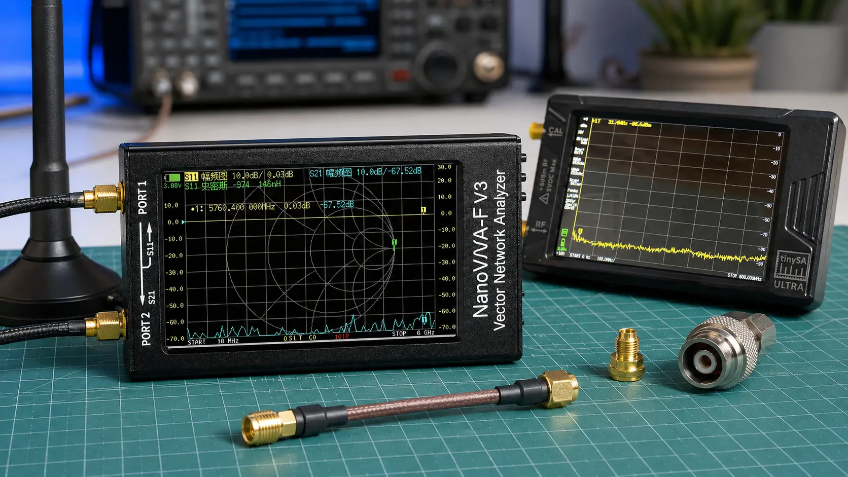
What Is S11?
S11 is the VNA reflection measurement at Port 1. For antenna testing, S11 is the main measurement because the antenna is normally connected to Port 1 of the NanoVNA.
S11 can be displayed in different formats:
| S11 display format | What it shows | Why it is useful |
|---|---|---|
| SWR | Standing wave ratio | Quick antenna match check. |
| LogMag | Reflection in dB | Return-loss-style view of antenna match. |
| Smith Chart | Complex impedance visually | Shows resistance, reactance, and tuning direction. |
| Resistance | Real impedance value | Shows how close the antenna is to 50 ohms resistance. |
| Reactance | Reactive impedance value | Shows capacitive or inductive behavior. |
| Phase | Phase of the reflection coefficient | Useful for advanced analysis. |
For beginner antenna testing, display SWR, S11 LogMag, and Smith Chart at the same time if your NanoVNA screen or software allows it.
What Is a Good Antenna Measurement?
A good antenna measurement depends on the system. A transmit antenna needs a safe match for the transmitter. A receive-only SDR antenna may work even with imperfect SWR, especially if it has enough signal and low noise.
| Application | Good target | Notes |
|---|---|---|
| Ham radio transmit antenna | Usually under 2:1 SWR, often better if possible | Check the radio manual and tuner limits. |
| SDR receive antenna | Good match helps, but signal-to-noise matters more | An antenna can receive usefully even if SWR is not perfect. |
| LoRa or Meshtastic antenna | Low SWR near 868 or 915 MHz | Bad matching can reduce range and stress transmitters. |
| ADS-B 1090 MHz antenna | Good match near 1090 MHz | Also check coax loss and antenna placement. |
| GNSS antenna | Correct antenna type and good RF path | Active antenna bias and cable loss often matter as much as match. |
| RF lab antenna | Defined match across the test band | Document SWR, return loss, impedance, and setup. |
How to Measure SWR, Impedance, and Return Loss with NanoVNA
Step 1: Set the frequency range
Set the start and stop frequencies around the band you actually care about. Do not sweep too wide if you need detailed tuning.
| Use case | Suggested sweep |
|---|---|
| 433 MHz antenna | 400–470 MHz |
| 868 MHz LoRa antenna | 820–900 MHz |
| 915 MHz LoRa antenna | 880–950 MHz |
| ADS-B antenna | 1000–1150 MHz |
| VHF ham antenna | 130–170 MHz |
| UHF ham antenna | 400–470 MHz |
Step 2: Calibrate at the reference plane
For antenna testing, use a one-port calibration on Port 1 with open, short, and load standards. The calibration should happen at the end of the cable where the antenna will connect, not only at the NanoVNA body, if you want to remove the feedline from the measurement.
Calibration choices matter:
- Calibrate at the NanoVNA port if you want to include the cable in the system measurement.
- Calibrate at the antenna end of the cable if you want to measure the antenna itself.
- Calibrate again if you change the frequency range significantly.
- Use good adapters and avoid moving cables after calibration.
Step 3: Set useful traces
Recommended traces:
- S11 SWR
- S11 LogMag
- Smith Chart
- Resistance and reactance if available
NanoVNA Saver or similar PC software can make this much easier because it gives a larger screen, better marker control, and cleaner screenshots.
Step 4: Place markers
Place markers at the frequencies that matter.
- Wanted operating frequency
- Lowest SWR point
- Band edges
- Resonance point where reactance crosses near zero
- Frequency where return loss is best
Step 5: Read the measurements together
Do not judge the antenna from only one number. Read the full picture:
- SWR: Is the match acceptable?
- Return loss: How much signal is reflected?
- Impedance: Is the antenna close to 50 + j0 ohms?
- Smith Chart: Is the antenna inductive, capacitive, too long, too short, or badly matched?
- Bandwidth: Is the antenna usable across the whole band or only at one narrow point?
Read the full practical guide: How to Test Antenna SWR with NanoVNA.
Smith Chart: Why It Helps
The Smith Chart looks confusing at first, but it is one of the best ways to understand impedance. The center of the Smith Chart is the target match, usually 50 ohms when normalized to a 50-ohm system.
When the trace is near the center, the antenna is well matched. When it moves away from the center, mismatch increases. The direction of movement helps show whether the antenna has inductive or capacitive reactance and whether tuning should move up or down in frequency.
Smith Chart helps answer:
- Is the antenna close to 50 ohms?
- Is the antenna inductive or capacitive?
- Is the antenna resonant but not matched?
- Does trimming the antenna move the trace in the right direction?
- Would a matching network help?
- Is the cable transforming the impedance?
For tuning antennas, the Smith Chart often tells you more than the SWR number.
Examples: Same SWR, Different Problems
Example 1: Antenna is resonant but not 50 ohms
Reading:
- SWR: 2.0:1
- Impedance: 25 + j0 ohms
This antenna is resonant because reactance is near zero, but resistance is not close to 50 ohms. Cutting the antenna length may not solve the match. A matching network or different antenna geometry may be needed.
Example 2: Antenna resistance is close but reactance is high
Reading:
- SWR: 2.0:1
- Impedance: 50 + j35 ohms
The resistance is close to 50 ohms, but reactance is causing mismatch. The antenna may need length adjustment, tuning, or compensation.
Example 3: Antenna is too narrowband
Reading:
- SWR: 1.2:1 at center frequency
- SWR: 3.0:1 at band edge
The antenna has a good match at one frequency but poor bandwidth. This may be fine for a fixed-frequency system, but poor for a wider-band radio or scanner.
Return Loss vs SWR: Which Should You Use?
Use both. SWR is easier for quick decisions, while return loss is better for engineering reports and precise comparison.
| Use SWR when | Use return loss when |
|---|---|
| You want a simple antenna tuning number. | You want a dB-based reflection measurement. |
| You are checking whether a radio can safely transmit. | You are comparing antennas, filters, or RF components more precisely. |
| You are helping beginners understand antenna match. | You are writing an RF report or lab document. |
| You only need a fast pass/fail check. | You are working with S-parameters and VNA data. |
A practical target such as “SWR under 2:1” is easy to communicate. A target such as “return loss better than 10 dB across the band” is often better for lab documentation.
What About Mismatch Loss?
Mismatch loss is the power loss caused by reflected energy not being delivered to the load. It is related to SWR and return loss, but it is not the same as coax cable loss.
| SWR | Reflected power | Approximate mismatch loss |
|---|---|---|
| 1.2:1 | 0.83% | 0.04 dB |
| 1.5:1 | 4.0% | 0.18 dB |
| 2.0:1 | 11.1% | 0.51 dB |
| 3.0:1 | 25.0% | 1.25 dB |
Important: mismatch loss is not the only concern. A high SWR can also make transmitters reduce power, create voltage/current stress, or make the system behave unpredictably. In receive-only systems, noise figure, antenna efficiency, and cable loss may matter more than mismatch loss alone.
SWR for Transmit vs Receive
Transmit systems
For transmitters, SWR matters because reflected power can stress the transmitter or cause it to reduce output power. Always check the radio manual. Many modern radios tolerate moderate mismatch, but that does not mean poor matching is ideal.
For transmit:
- Keep SWR within the radio’s safe range.
- Check the full operating band, not only one frequency.
- Use a proper dummy load for transmitter checks.
- Do not transmit into unknown antennas or damaged cables.
- Check coax loss and connector quality.
Receive-only SDR systems
For receive-only systems, a perfect SWR is not always required. Some wideband receive antennas have imperfect SWR but still work well because they capture enough signal across a wide range.
For SDR receiving, focus on:
- Signal-to-noise ratio
- Antenna placement
- Correct antenna type
- Coax cable loss
- Nearby interference
- Receiver overload
- Filters and LNAs where useful
Read: Do You Need an LNA for SDR?.
Practical Measurement Targets by Use Case
| Use case | Good target | Extra notes |
|---|---|---|
| LoRa / Meshtastic | Low SWR near 868 or 915 MHz | Also check antenna placement and coax loss. |
| ADS-B 1090 MHz | Good match near 1090 MHz | Cable loss and antenna height are often more important than tiny SWR differences. |
| VHF/UHF ham radio | Usually under 2:1 across the intended transmit band | Lower is better, but check radio manual and tuner behavior. |
| CB antenna | Best SWR near chosen channel range | Whip length and ground plane strongly affect results. |
| Wideband SDR receive antenna | Reasonable match across broad range | Do not expect perfect SWR everywhere. |
| GNSS active antenna | Correct antenna, cable, bias, and placement | Do not judge only by SWR; active antenna electronics matter. |
| RF lab antenna | Documented SWR, return loss, impedance, and setup | Repeatability matters more than only getting one low number. |
Common Antenna Measurement Mistakes
Measuring without calibration
Always calibrate the NanoVNA over the frequency range you want to measure. For antenna testing, use open, short, and load on Port 1.
Calibrating at the wrong reference plane
If you calibrate at the NanoVNA body and then add a long cable, you are measuring the antenna plus cable. If you calibrate at the antenna end of the cable, you are measuring mostly the antenna.
Only looking at the lowest SWR point
The lowest SWR point may not be the frequency you need. Always place a marker at the actual operating frequency.
Ignoring impedance
SWR says whether the match is good. Impedance says why it is good or bad.
Confusing return loss sign
NanoVNA may show S11 LogMag as a negative value, such as -14 dB. That corresponds to about 14 dB return loss. More negative S11 LogMag is better.
Touching the antenna during measurement
Your hand and body can detune small antennas, especially VHF, UHF, LoRa, and handheld antennas. Keep the antenna in a realistic position.
Testing an antenna indoors and expecting outdoor results
Walls, desks, metal objects, laptops, windows, and your body can change antenna behavior. Test in a realistic installation position when possible.
Ignoring coax cable loss
A good antenna with a bad cable can still perform poorly. Measure coax cable loss separately with S21.
Read: How to Test Coax Cable Loss with a NanoVNA.
NanoVNA vs SWR Meter vs Spectrum Analyzer
| Tool | Best for | Limitation |
|---|---|---|
| NanoVNA | SWR, impedance, return loss, Smith Chart, cable loss, filters | Requires calibration and correct setup. |
| Basic SWR meter | Quick transmitter and antenna match checks | Usually does not show impedance or Smith Chart. |
| TinySA Ultra | Seeing RF signals, interference, harmonics, and spectrum activity | Does not measure antenna SWR or impedance like a VNA. |
| Professional VNA | Higher-confidence S-parameter and impedance measurements | More expensive and often less convenient for beginners. |
For antenna matching, use NanoVNA or another antenna analyzer. For signal presence and interference, use TinySA Ultra or a spectrum analyzer.
Read: NanoVNA vs TinySA: Which RF Tool Do You Actually Need?.
How to Document Antenna Measurements
A useful antenna test report should include more than one screenshot.
- Antenna model or description
- Frequency range tested
- NanoVNA model
- Calibration method
- Reference plane location
- Cable and adapters used
- Antenna location and orientation
- SWR at operating frequency
- Return loss at operating frequency
- Impedance at operating frequency
- Lowest SWR frequency
- Usable bandwidth target
- Smith Chart screenshot
- Environmental notes
Recommended SDRstore.eu Hardware Packages
Package 1: Beginner antenna measurement kit
- NanoVNA-H4
- Open, short, load calibration kit
- Short SMA cables
- SMA adapter set
- Example antennas for testing
Best for: SDR beginners, ham radio users, antenna builders, LoRa/Meshtastic users, and students learning SWR and impedance.
Package 2: SDR antenna troubleshooting kit
- NanoVNA-H4
- TinySA Ultra
- RTL-SDR receiver
- Band-specific antennas
- Filters and LNAs where needed
- Coax cables and adapters
Best for: comparing antenna match with real-world received signal strength and interference.
Package 3: Ham radio antenna analyzer kit
- NanoVNA-H4 or higher-grade antenna analyzer
- Calibration standards
- Common adapter set
- Coax jumper set
- Dummy load
- Outdoor antenna test checklist
Best for: VHF/UHF antennas, CB antennas, portable whips, dipoles, verticals, and field antenna tuning.
Package 4: RF lab measurement kit
- NanoVNA-H4 or higher-grade VNA
- TinySA Ultra or professional spectrum analyzer
- RF power meter
- Dummy loads
- Attenuators
- Filters
- Known-good cables and adapters
- Measurement report templates
Best for: universities, RF labs, product testing, antenna development, and wireless-security training.
Purchase-Order Justification Examples
NanoVNA antenna measurement justification
NanoVNA-H4 is required to measure antenna SWR, impedance, return loss, S11, Smith Chart response, coax cable loss, and filter behavior for SDR, ham radio, LoRa, GNSS, ADS-B, and RF lab applications.
TinySA Ultra complementary measurement justification
TinySA Ultra is required to complement NanoVNA antenna measurements by showing real RF spectrum activity, interference, signal presence, harmonics, and field conditions around the antenna system.
RF adapter and cable justification
Calibration standards, known-good cables, adapters, dummy loads, and RF accessories are required to create repeatable antenna measurements and reduce errors caused by poor connectors or incorrect reference planes.
Professional antenna analyzer justification
A professional antenna analyzer or VNA is required when antenna measurements need higher confidence, wider frequency coverage, better calibration, field reporting, or production validation.
Request a Quote for Antenna Measurement Equipment
Universities, RF labs, ham radio clubs, SDR users, LoRa and Meshtastic groups, cybersecurity teams, telecom labs, product-testing teams, and public-sector buyers can request a formal quotation directly from SDRstore.eu.
Use the Add to Quote button on product pages or the document icon on product cards. Add NanoVNA-H4, TinySA Ultra, antennas, cables, adapters, dummy loads, attenuators, RF power meters, filters, SDR receivers, and project notes to one quote request.
A quote request is useful when you need:
- NanoVNA antenna measurement kits
- SWR and impedance testing tools
- Return-loss measurement hardware
- Ham radio antenna analyzer kits
- LoRa and Meshtastic antenna testing bundles
- ADS-B and GNSS antenna validation tools
- University RF teaching kits
- Formal pricing for company, university, or public-sector procurement
Read the SDRstore.eu quote-request guide.
Related SDRstore.eu Guides
- NanoVNA Setup Guide: Calibration, SWR, Smith Chart, and Antenna Testing
- How to Test Antenna SWR with NanoVNA
- How to Test Coax Cable Loss with a NanoVNA
- How to Test RF Filters with a NanoVNA
- NanoVNA vs TinySA: Which RF Tool Do You Actually Need?
- Best Antenna Analyzer for Ham Radio
- Best SDR for ADS-B: RTL-SDR Kits, Antennas, Filters, and LNAs Compared
- Meshtastic Range Guide
- Do You Need an LNA for SDR?
- SDR Hardware for RF Product Testing
Official and Technical Resources
- Rohde & Schwarz: VSWR and return loss
- Rohde & Schwarz: VNA antenna measurement
- Keysight VSWR and return loss calculator
- Keysight reflection measurements
- Keysight network analyzer overview
- NanoVNA beginner guide
- NanoVNA V2 user manual
- NanoVNA Saver
Final Recommendation
Use SWR for a quick antenna match check, return loss for a cleaner dB-based reflection measurement, and impedance to understand the actual cause of the mismatch. For serious antenna tuning, do not rely on only one number.
With a NanoVNA, start with a proper one-port calibration, connect the antenna to Port 1, display SWR, S11 LogMag, and Smith Chart, then place markers at the frequencies you actually use. Look for a good match, low reactance, reasonable resistance near 50 ohms, and enough bandwidth across the operating band.
The best antenna measurement is not “lowest SWR anywhere.” It is the antenna behaving correctly at the frequency you need, in the installation position you will actually use, with the cable and RF path properly understood.
FAQ
What is the difference between SWR and impedance?
SWR tells you how well the antenna system is matched, while impedance tells you the actual resistance and reactance causing that match or mismatch. SWR is the result; impedance helps explain why.
What is the difference between SWR and return loss?
SWR and return loss both describe reflection. SWR is a ratio, while return loss expresses reflection in dB. Lower SWR is better, while higher return loss is better.
What is a good SWR?
1:1 is perfect, 1.2:1 is excellent, 1.5:1 is good, and 2:1 is often usable but not ideal. For transmitters, always check the radio manual and safe operating limits.
What is a good return loss?
10 dB return loss is often a practical minimum, 14 dB is roughly similar to 1.5:1 SWR, 20 dB is good, and 30 dB is excellent if measured correctly.
What impedance should an antenna have?
Most SDR, ham radio, LoRa, ADS-B, GNSS, and RF test systems are designed around 50 ohms. A well-matched antenna is usually close to 50 + j0 ohms at the target frequency.
What does 50 + j0 ohms mean?
It means 50 ohms resistance and zero reactance. This is the ideal match for most 50-ohm RF systems at that specific frequency.
What is S11 on a NanoVNA?
S11 is the Port 1 reflection measurement. For antenna testing, it can be displayed as SWR, return-loss-style LogMag, Smith Chart, impedance, resistance, reactance, or phase.
Why does NanoVNA show return loss as a negative number?
NanoVNA often shows S11 LogMag as a negative dB value. For example, S11 = -20 dB corresponds to about 20 dB return loss. More negative S11 LogMag usually means a better match.
Is low SWR always the best antenna?
No. Low SWR only means the antenna system is matched at that frequency. Antenna efficiency, radiation pattern, placement, cable loss, noise, and signal-to-noise ratio also matter.
Can SDRstore.eu quote a NanoVNA antenna measurement kit?
Yes. Use the Add to Quote button on product pages or the document icon on product cards. Add NanoVNA-H4, TinySA Ultra, antennas, cables, adapters, dummy loads, attenuators, and project notes so the full antenna measurement setup can be quoted together.
No posts found
Write a review
We support all major card and digital payment options. More local methods are available and shown during checkout.
You enter into a binding sales contract once you have received an 'order confirmation and sales receipt' email from us, in line with our Sales & Delivery conditions. Therefore, sdrstore.eu has the right to cancel your order in the event of technical problems, delivery failure, Fair use policy and other similar situations.
Your payments are protected by advanced encryption and 3-D Secure authentication for safe online shopping.