
How to Test Coax Cable Loss with a NanoVNA
Coax cable loss is one of the easiest RF problems to ignore and one of the easiest RF problems to measure. A receiver may be good, the antenna may be tuned, and the software may be configured correctly, but a long or poor-quality coax cable can still remove a large part of the signal before it reaches the radio.
A NanoVNA is a practical tool for testing coax cable loss because it can measure S21 insertion loss across frequency. With a proper calibration, you can see how much signal is lost through a coax cable at 145 MHz, 433 MHz, 868 MHz, 915 MHz, 1090 MHz, 1575 MHz, 2.4 GHz, or any other frequency inside your NanoVNA’s usable range.
This guide explains how to test coax cable loss with a NanoVNA, including the direct S21 method, one-port round-trip method, calibration, markers, one-way loss, return loss, cable quality, connector problems, and how to decide whether a coax cable is suitable for SDR, ham radio, LoRa, ADS-B, GNSS, RF labs, or facility monitoring.
Browse the NanoVNA-H4 portable vector network analyzer, spectrum analyzers and RF analysis tools, RF power meters, RF dummy loads, RF test and measurement equipment, and request a formal quote from SDRstore.eu.
Quick Answer: How Do You Test Coax Cable Loss with a NanoVNA?
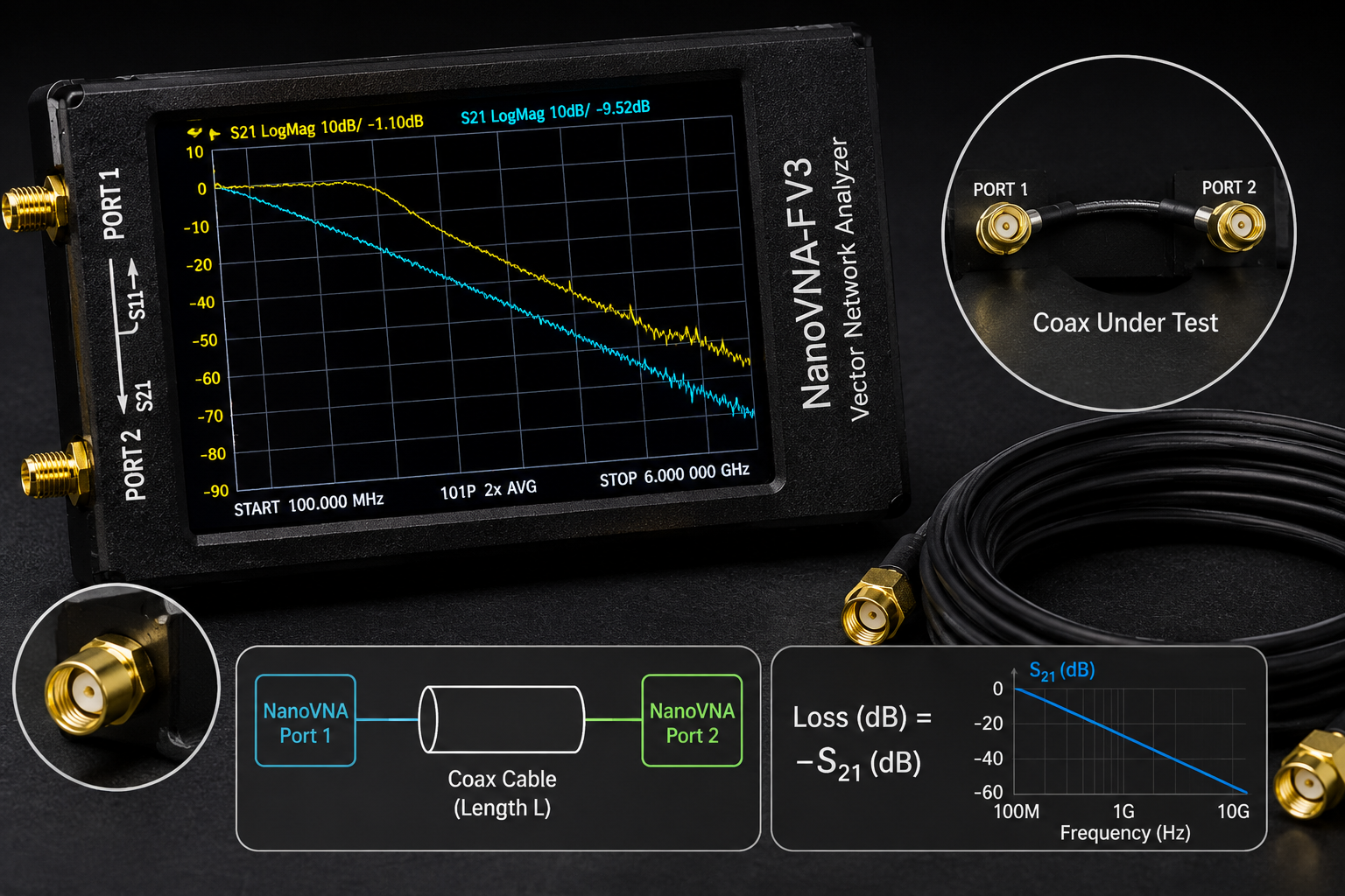
The best way to test coax cable loss with a NanoVNA is to perform a two-port S21 measurement. Calibrate the NanoVNA across the frequency range you want to test, connect the coax cable between Port 1 and Port 2, display S21 LOGMAG, and place markers at the frequencies you care about. The negative dB value on S21 is the cable’s one-way insertion loss at that frequency.
| Measurement method | What it measures | Best use |
|---|---|---|
| S21 two-port method | Direct one-way insertion loss through the coax cable | Best normal method for measuring coax cable loss. |
| S11 one-port open/short method | Round-trip loss estimate down the cable and back | Useful when the far end cannot be connected to Port 2, but less direct. |
| S11 return-loss check with 50 ohm load | Cable and connector match/reflection behavior | Useful for finding bad connectors, damaged cable, or impedance problems. |
| TDR or time-domain mode where available | Approximate distance to cable faults or impedance changes | Useful for troubleshooting damaged long cables. |
For most users, use S21. It is direct, simple, and gives the cable loss you actually care about.
What Is Coax Cable Loss?
Coax cable loss is the amount of RF signal lost as it travels through the cable. It is usually expressed in dB. A longer cable loses more signal than a shorter cable, and the same cable usually loses more signal at higher frequencies.
That means a cable that works fine at HF or VHF may be poor at 868 MHz, 1090 MHz, 1575 MHz, 2.4 GHz, or 5.8 GHz.
| Frequency range | Why cable loss matters |
|---|---|
| HF | Cable loss is usually lower, but long cables and poor connectors can still matter. |
| VHF | Loss becomes more important for antennas, repeaters, airband, AIS, and ham radio. |
| UHF | Loss can become significant, especially with thin cables such as RG174. |
| 868/915 MHz | LoRa, Meshtastic, and IoT range can be reduced by long or poor coax runs. |
| 1090 MHz | ADS-B systems can lose aircraft range if the coax between antenna and receiver is too lossy. |
| 1575 MHz | GNSS reception is sensitive, so cable loss and active-antenna biasing matter. |
| 2.4 GHz and above | Cable loss becomes a major design factor; short, low-loss cable is strongly preferred. |
Why Coax Loss Matters for SDR and RF Projects
In a receive system, cable loss reduces the signal before it reaches the receiver. If the loss happens before an LNA, it can reduce the usable signal-to-noise ratio. In a transmit system, cable loss reduces the power that reaches the antenna and wastes power as heat.
Common symptoms of excessive cable loss include:
- Short ADS-B aircraft range
- Poor LoRa or Meshtastic range
- Weak GNSS reception
- Low satellite signal strength
- VHF/UHF antenna performs worse than expected
- Signal improves when the receiver is moved closer to the antenna
- LNA helps only when placed near the antenna, not near the SDR
- High-frequency signals disappear through long thin cable
Read also: Do You Need an LNA for SDR?
Method 1: Direct S21 Coax Cable Loss Measurement
The direct S21 method is the best normal method for measuring coax cable loss with a NanoVNA. It measures how much signal passes through the cable from Port 1 to Port 2.
What you need
- NanoVNA or NanoVNA-H4
- Open, short, load, and through calibration standards
- The coax cable you want to test
- Adapters only if required
- Optional short known-good test cables
- Optional NanoVNA Saver or PC software for screenshots
Basic connection
- NanoVNA Port 1 → coax cable under test → NanoVNA Port 2
If the cable is too long to place directly between both ports, bring both ends to the NanoVNA temporarily or use the one-port method later in this guide.
Step-by-step S21 method
- Set the start and stop frequency for the range you want to test.
- Set one trace to S21 LOGMAG.
- Perform a two-port calibration across that range.
- Use the through calibration step to remove the loss of the test leads and adapters where possible.
- Connect the coax cable under test between Port 1 and Port 2.
- Place markers at the frequencies you care about.
- Read the S21 value at each marker.
If S21 reads -1.5 dB at 1090 MHz, the cable has about 1.5 dB one-way loss at 1090 MHz in that measurement setup.
Recommended Frequency Markers
Set markers at the frequencies your system actually uses. A single cable-loss number is not enough because cable loss changes with frequency.
| Use case | Marker frequency | Why it matters |
|---|---|---|
| 2m ham radio | 144–146 MHz | Checks VHF antenna feedline loss. |
| 70cm ham radio | 430–440 MHz | Checks UHF feedline loss. |
| Sub-GHz remote and sensors | 315 MHz or 433.92 MHz | Useful for Sub-GHz monitoring and IoT devices. |
| LoRa EU868 | 868 MHz | Important for LoRa, Meshtastic, and industrial sensors in Europe. |
| LoRa US915 | 915 MHz | Important for LoRa, Meshtastic, and ISM devices in supported regions. |
| ADS-B | 1090 MHz | Cable loss can significantly affect aircraft reception range. |
| GNSS L1 | 1575.42 MHz | Useful for GPS/Galileo L1/E1 receive setups if within the VNA range. |
| WiFi/BLE/Zigbee | 2.4 GHz | Requires a VNA that supports the frequency; many basic NanoVNA models do not reach this range accurately. |
How to Choose the NanoVNA Sweep Range
Do not always sweep the entire NanoVNA range. Choose a range that gives useful detail around the frequencies you care about.
| Project | Suggested sweep | Reason |
|---|---|---|
| VHF/UHF radio cable | 100–500 MHz | Shows how loss rises from VHF to UHF. |
| 433 MHz sensor cable | 300–500 MHz | Focuses on the Sub-GHz band of interest. |
| LoRa 868/915 cable | 700–1000 MHz | Shows loss near both LoRa regions. |
| ADS-B cable | 900–1200 MHz | Shows loss around 1090 MHz. |
| GNSS cable | 1400–1700 MHz | Useful only if your NanoVNA is specified and reliable in that range. |
| General cable comparison | 10 MHz–1.5 GHz | Shows the overall trend, but with less detail per band. |
Calibrate after setting the sweep. If you change the start and stop frequencies significantly, calibrate again.
How to Read the S21 Cable-Loss Result
On the S21 LOGMAG trace, cable loss appears as a negative dB number.
| S21 reading | Cable-loss meaning | Practical interpretation |
|---|---|---|
| -0.2 dB | Very low loss | Excellent for most receive setups. |
| -0.5 dB | Low loss | Good result, especially at higher frequencies. |
| -1 dB | Moderate loss | Usually acceptable for many receive systems. |
| -3 dB | Half the power is lost | Important loss; may be acceptable only if unavoidable. |
| -6 dB | About three quarters of the power is lost | Too much for many weak-signal receive systems. |
| -10 dB | Very large loss | Usually a serious problem unless the cable is intentionally lossy. |
For receive systems such as ADS-B, GNSS, satellite reception, LoRa, and weak-signal SDR monitoring, even a few dB of cable loss can matter.
One-Way Loss vs Round-Trip Loss
The S21 method gives one-way cable loss directly. This is normally what you want.
The one-port S11 open/short method measures a signal that travels down the cable and back. That is round-trip loss. To estimate one-way loss, divide the measured round-trip loss by two.
| Method | Signal path | How to interpret |
|---|---|---|
| S21 method | Port 1 → cable → Port 2 | Reading is direct one-way cable loss. |
| S11 open/short method | Port 1 → cable end → reflection → Port 1 | Approximate one-way loss is half the round-trip loss. |
Example: if the one-port method shows around 6 dB round-trip loss, the cable’s approximate one-way loss is around 3 dB. This method is useful, but S21 is still preferred when both ends of the cable can reach the NanoVNA.
Method 2: One-Port Cable Loss Estimate
The one-port method is useful when the cable is already installed and the far end cannot easily be connected to Port 2. It uses S11 reflection behavior with the far end open or shorted.
When to use this method
- The cable is installed through a wall, mast, roof, or vehicle.
- Only one end of the cable is accessible at the test position.
- You need a quick field estimate.
- You are checking a long antenna feedline.
- You are troubleshooting possible cable damage.
Basic workflow
- Disconnect the antenna or device from the far end of the cable.
- Leave the far end open or short it with a suitable connector, depending on the method you prefer.
- Calibrate NanoVNA Port 1 at the near end.
- Connect the cable to Port 1.
- Display S11 LOGMAG.
- Read the round-trip loss behavior at the frequency of interest.
- Estimate one-way loss by dividing round-trip loss by two.
Limitations
- It is an estimate, not the cleanest direct method.
- Bad cable impedance can make the result misleading.
- Connector reflections can affect the trace.
- Low-loss cables can be harder to estimate accurately.
- Direct S21 is preferred where possible.
Method 3: Check Cable Return Loss and Connector Problems
Cable loss is not the only thing that matters. A cable can have acceptable loss but still have bad connectors, poor shielding, water ingress, crushed sections, or impedance problems.
To check return loss, terminate the far end of the cable with a good 50-ohm load and measure S11 from the near end.
What you need
- NanoVNA Port 1
- Cable under test
- Good 50-ohm load at the far end
- Open/short/load calibration at the near end
What to look for
- Good return loss across the intended band
- No sudden dips or spikes caused by faults
- No strong ripple from connector mismatch
- No large impedance discontinuities
- Stable result when the cable is moved gently
If the S11 result changes when you move the connector, the problem may be the connector, not the cable type.
How Much Coax Loss Is Acceptable?
There is no universal answer. Acceptable loss depends on the system, signal strength, antenna gain, receiver sensitivity, noise floor, LNA placement, and whether the system is receive-only or transmit-capable.
| Measured one-way loss | Receive-system impact | Recommendation |
|---|---|---|
| Under 0.5 dB | Excellent | Usually no concern. |
| 0.5–1 dB | Low to moderate | Usually acceptable. |
| 1–3 dB | Noticeable | May be acceptable, but consider shorter or better cable for weak signals. |
| 3–6 dB | Significant | Use better coax, shorter cable, or an LNA near the antenna for receive systems. |
| Over 6 dB | Large loss | Usually a major problem for weak-signal RF reception. |
For weak-signal receiving, put any LNA near the antenna before the lossy cable. An LNA at the receiver end cannot fully recover signal-to-noise ratio already lost in the cable.
Cable Loss by Application
ADS-B at 1090 MHz
ADS-B reception depends heavily on antenna height and coax quality. A long thin cable can reduce aircraft range even when the antenna is placed well.
For ADS-B:
- Measure cable loss at 1090 MHz.
- Keep cable as short as practical.
- Use low-loss coax for outdoor antennas.
- Consider an LNA near the antenna if the cable is long.
- Use weatherproof outdoor connections.
Read: Best SDR for ADS-B: RTL-SDR Kits, Antennas, Filters, and LNAs Compared.
LoRa and Meshtastic at 868/915 MHz
LoRa and Meshtastic users often mount antennas higher for range. That can help, but long coax can remove part of the benefit.
For LoRa and Meshtastic:
- Measure cable loss at 868 MHz or 915 MHz.
- Avoid long thin coax runs.
- Use low-loss coax for outdoor base stations.
- Consider placing the radio closer to the antenna in a weatherproof enclosure.
- Check antenna SWR separately with NanoVNA.
Read: Meshtastic Range Guide.
GNSS at 1575 MHz
GNSS signals are weak, and many GNSS antennas are active antennas that need power through the coax. Cable loss, bias-tee compatibility, and antenna placement all matter.
For GNSS:
- Measure cable loss near 1575 MHz if your VNA supports that range reliably.
- Use an active GNSS antenna when needed.
- Confirm bias voltage and current requirements.
- Avoid unnecessary adapters.
- Weatherproof outdoor antenna connections.
Read: GNSS Spoofing Detection with SDR.
VHF/UHF ham radio
At VHF and UHF, coax loss affects both transmit and receive. It is especially important for long mast runs and portable setups.
For ham radio:
- Measure cable loss at the operating band.
- Check antenna SWR separately.
- Use suitable low-loss coax for long outdoor runs.
- Inspect connectors after outdoor use.
- Replace damaged or water-filled cable.
Read: How to Test Antenna SWR with NanoVNA.
What Cable Problems Can a NanoVNA Reveal?
| Problem | Possible NanoVNA clue | What to do |
|---|---|---|
| High cable loss | S21 is much lower than expected | Use shorter or lower-loss cable. |
| Bad connector | Trace changes when connector is moved | Replace or re-terminate connector. |
| Wrong impedance cable | Poor S11 with 50-ohm load, ripple, mismatch | Use correct 50-ohm coax for RF systems. |
| Water ingress | Higher loss, unstable readings, poor match | Replace cable and improve weatherproofing. |
| Crushed or kinked cable | Return-loss ripple or impedance discontinuity | Inspect physically and replace damaged section. |
| Too many adapters | Extra loss and mismatch | Use fewer adapters and correct connector types. |
| Counterfeit or unknown cable | Loss much worse than expected | Compare against known-good cable. |
NanoVNA Cable Test vs Cable Datasheet
Cable datasheets are useful, but real installed cable may perform worse because of connector quality, adapters, bends, water ingress, age, damage, and installation mistakes.
Measure the actual cable when:
- The cable type is unknown.
- The cable is old.
- The cable was installed outdoors.
- The cable has many adapters.
- Reception is worse than expected.
- You are comparing two antenna locations.
- You are building a serious ADS-B, LoRa, GNSS, or RF monitoring setup.
The real measurement matters more than the label on the cable.
Common NanoVNA Coax Loss Testing Mistakes
Forgetting through calibration
For direct S21 measurement, the through calibration step is important. It helps remove the loss of the test leads and adapters used during calibration.
Changing cables after calibration
Calibration is valid for the test setup used during calibration. If you move cables significantly or change adapters, the measurement can change.
Testing outside the reliable frequency range
Do not assume every NanoVNA is equally accurate at every displayed frequency. If you need higher-frequency cable testing, choose a VNA that covers the target band properly.
Using too many adapters
Adapters add loss and mismatch. Use the minimum number of adapters and use good-quality connectors.
Confusing one-way and round-trip loss
S21 gives one-way loss. One-port open/short methods estimate round-trip loss, so one-way loss is approximately half the value.
Ignoring cable flex
If the trace changes when you gently move the cable or connector, the cable may be damaged or the connector may be bad.
Judging the cable at only one frequency
Cable loss rises with frequency. Test at every band you actually use.
Testing an active device like a passive cable
Do not test powered LNAs, active antennas, or biased devices as if they are passive coax cables. Check bias voltage, input limits, and safe RF setup first.
How to Document a Coax Cable Loss Measurement
A useful cable test report should include enough information to repeat the measurement.
- Cable type if known
- Cable length
- Connector types
- Adapters used
- NanoVNA model
- Calibration range
- Calibration method
- Measurement method: S21 or one-port estimate
- Marker frequencies
- Measured loss at each marker
- Return-loss notes if checked
- Condition of cable and connectors
- Whether cable is indoor, outdoor, old, or newly installed
- Screenshot or NanoVNA Saver export
Example Cable Loss Report Format
| Frequency | Measured S21 | Interpretation |
|---|---|---|
| 433 MHz | -0.8 dB | Good for Sub-GHz monitoring. |
| 868 MHz | -1.4 dB | Acceptable, but loss is now noticeable. |
| 1090 MHz | -2.1 dB | May reduce ADS-B range; consider shorter or better coax. |
| 1575 MHz | -3.2 dB | Significant for passive GNSS; active antenna or lower-loss cable may be needed. |
These are example values only. Always measure your actual cable.
How to Reduce Coax Cable Loss
- Use the shortest practical cable.
- Use lower-loss coax for higher frequencies.
- Move the receiver closer to the antenna when possible.
- Use an LNA near the antenna for weak-signal receive systems.
- Avoid unnecessary adapters.
- Use weatherproof outdoor connectors.
- Avoid sharp bends and crushed cable.
- Replace old or water-damaged cable.
- Use correct 50-ohm coax for most SDR and RF test setups.
- Measure the final installed cable, not only a new cable on the bench.
NanoVNA vs TinySA for Coax Testing
NanoVNA and TinySA Ultra solve different RF problems.
| Question | Best tool | Why |
|---|---|---|
| How much loss does this coax cable have? | NanoVNA | S21 directly measures insertion loss. |
| Is the cable or connector mismatched? | NanoVNA | S11 shows return loss and reflections. |
| Is there a signal in the air? | TinySA Ultra or spectrum analyzer | Shows live RF energy. |
| Does replacing the cable improve reception? | Both | NanoVNA measures cable loss; TinySA or SDR shows real-world signal change. |
| Is the antenna tuned? | NanoVNA | S11/SWR/Smith Chart measure antenna match. |
For best results, use NanoVNA to measure the cable and antenna system, then use TinySA Ultra or an SDR receiver to confirm the real signal improvement.
Recommended SDRstore.eu Hardware Packages
Package 1: Beginner coax cable testing kit
- NanoVNA-H4
- Open, short, load, through calibration kit
- Short SMA test cables
- SMA adapters
- Known-good reference coax cable
Best for: SDR beginners, ham radio users, antenna setups, and basic cable comparison.
Package 2: SDR antenna feedline troubleshooting kit
- NanoVNA-H4
- TinySA Ultra
- RTL-SDR receiver
- Band-specific antennas
- Filters and LNAs where needed
- Short and long cable comparison set
Best for: ADS-B, LoRa, Meshtastic, GNSS receive checks, VHF/UHF monitoring, and antenna placement decisions.
Package 3: RF lab cable validation kit
- NanoVNA-H4 or higher-grade VNA
- TinySA Ultra or spectrum analyzer
- RF power meter
- Dummy loads
- Attenuators
- DC blocks
- Adapters and known-good short test cables
- Measurement log template
Best for: universities, RF labs, cybersecurity labs, product testing, and controlled RF cyber range setups.
Package 4: Outdoor antenna installation kit
- NanoVNA-H4
- Weatherproof coax cable and connectors
- Band-specific outdoor antenna
- Lightning protection where required
- Low-loss cable for high-frequency runs
- Weatherproofing tape and strain relief
- Final installed cable-loss and SWR test checklist
Best for: ADS-B, LoRa gateways, ham radio, AIS, VHF/UHF receive stations, and facility monitoring antennas.
Purchase-Order Justification Examples
NanoVNA cable-loss testing justification
NanoVNA-H4 is required to measure coax cable loss, S21 insertion loss, S11 return loss, antenna feedline performance, connector quality, and RF path behavior for SDR, antenna, RF lab, and wireless monitoring installations.
TinySA Ultra field validation justification
TinySA Ultra is required to confirm real RF signal levels before and after cable or antenna changes, investigate interference, and support field troubleshooting alongside NanoVNA cable measurements.
RF power meter and dummy load justification
RF power meters and dummy loads are required to verify transmitter power, safely terminate RF outputs, protect test equipment, and support controlled RF bench measurements.
RF cable and adapter justification
Known-good coax cables, SMA adapters, calibration standards, attenuators, and DC blocks are required to create repeatable cable-loss measurements and reduce errors caused by poor connectors or unsafe RF paths.
Request a Quote for NanoVNA and Coax Cable Testing Equipment
Universities, RF labs, ham radio clubs, SDR users, cybersecurity teams, telecom labs, IoT developers, facility monitoring teams, and product-testing teams can request a formal quotation directly from SDRstore.eu.
Use the Add to Quote button on product pages or the document icon on product cards. Add NanoVNA-H4, TinySA Ultra, RF power meters, dummy loads, attenuators, antennas, filters, SDR receivers, cables, adapters, and project notes to one quote request.
A quote request is useful when you need:
- NanoVNA coax cable loss testing kits
- ADS-B antenna feedline test equipment
- LoRa and Meshtastic cable-loss measurement tools
- GNSS antenna cable validation tools
- Ham radio coax and antenna testing kits
- RF lab cable validation hardware
- University RF teaching kits
- Formal pricing for company, university, or public-sector procurement
Read the SDRstore.eu quote-request guide.
Related SDRstore.eu Guides
- NanoVNA Setup Guide: Calibration, SWR, Smith Chart, and Antenna Testing
- How to Test Antenna SWR with NanoVNA
- How to Test RF Filters with a NanoVNA
- NanoVNA vs TinySA: Which RF Tool Do You Actually Need?
- TinySA vs Professional Spectrum Analyzer
- Best SDR for ADS-B: RTL-SDR Kits, Antennas, Filters, and LNAs Compared
- Do You Need an LNA for SDR?
- SDR Hardware for RF Product Testing
- RF Spectrum Monitoring for Facilities, Labs, and Critical Infrastructure
- RF Cyber Range Hardware
Official and Technical Resources
- NanoVNA basics
- NanoVNA start measurement guide
- NanoVNA Vector Network Analyzer User Guide
- Rohde & Schwarz: How to measure cable loss
- Keysight vector network analyzer overview
- Keysight network analysis fundamentals
- Rohde & Schwarz: Understanding S-parameters
Final Recommendation
Use the NanoVNA S21 method whenever both ends of the coax cable can be connected between Port 1 and Port 2. It gives the direct one-way insertion loss of the cable at each frequency marker.
Use the one-port open/short method only when the cable is already installed and the far end cannot be brought back to the NanoVNA. It can estimate cable loss, but it is less direct and the measured value is round-trip loss, so one-way loss is approximately half.
For serious SDR, ADS-B, LoRa, GNSS, ham radio, and RF monitoring setups, do not guess cable loss. Measure it. A better antenna position is useful only if the coax cable does not remove too much of the signal before it reaches the receiver.
FAQ
Can NanoVNA measure coax cable loss?
Yes. NanoVNA can measure coax cable loss using an S21 transmission measurement. Connect the coax cable between Port 1 and Port 2, calibrate across the target frequency range, and read the S21 LOGMAG value at your marker frequencies.
Which NanoVNA trace should I use for cable loss?
Use S21 LOGMAG. S21 shows transmission through the cable, so the negative dB value is the cable’s one-way insertion loss at that frequency.
Is S21 cable loss one-way or round-trip?
S21 cable loss is one-way loss from Port 1 to Port 2. That is the normal value you want for cable-loss planning.
How do I measure cable loss if only one end of the cable is accessible?
You can use a one-port S11 open or short method to estimate round-trip loss. Because the signal travels down the cable and back, the approximate one-way loss is half the measured round-trip loss. Direct S21 is still preferred when possible.
Why does coax cable loss increase with frequency?
Coax loss increases with frequency because conductor loss, dielectric loss, and skin-effect-related behavior become more significant at higher frequencies. This is why cable choice matters more at 868 MHz, 1090 MHz, 1575 MHz, and 2.4 GHz than at lower frequencies.
How much coax loss is too much?
For weak-signal receiving, under 1 dB is usually very good, 1–3 dB is noticeable, 3–6 dB is significant, and over 6 dB is usually a major problem. The exact limit depends on the system.
Can NanoVNA find a bad coax connector?
Yes, it can help. Bad connectors may appear as poor return loss, unstable readings, ripple, or measurement changes when the connector is moved gently.
Can NanoVNA test long outdoor antenna cables?
Yes. Use direct S21 if both ends can be connected to the NanoVNA. If only one end is accessible, use the one-port method for an estimate and check return loss with a good 50-ohm load at the far end.
Should I test coax loss at one frequency or many?
Test every frequency band you use. A cable may be acceptable at 145 MHz but poor at 868 MHz, 1090 MHz, or 1575 MHz.
Can SDRstore.eu quote a NanoVNA coax cable testing kit?
Yes. Use the Add to Quote button on product pages or the document icon on product cards. Add NanoVNA-H4, TinySA Ultra, RF power meters, dummy loads, attenuators, cables, adapters, antennas, filters, and project notes so the full cable testing setup can be quoted together.
No posts found
Write a review
We support all major card and digital payment options. More local methods are available and shown during checkout.
You enter into a binding sales contract once you have received an 'order confirmation and sales receipt' email from us, in line with our Sales & Delivery conditions. Therefore, sdrstore.eu has the right to cancel your order in the event of technical problems, delivery failure, Fair use policy and other similar situations.
Your payments are protected by advanced encryption and 3-D Secure authentication for safe online shopping.