





Passive Radar with SDR: Hardware, Coherent Receivers, Antennas, and Real-World Research
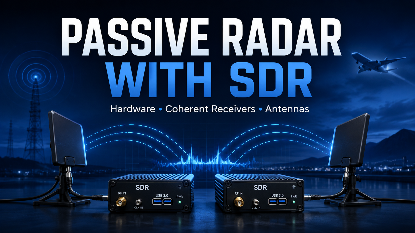
Radar normally brings to mind a transmitter sending powerful RF pulses and then listening for reflections.
Passive radar works differently.
Instead of transmitting its own waveform, a passive radar receiver listens to radio signals that already exist in the environment. Broadcast FM, digital radio, digital television and other communications transmitters can become illuminators of opportunity.
A coherent SDR system receives both a clean reference copy of the original transmission and reflections arriving from the surrounding environment. Signal processing then compares the two channels to identify changes in delay and Doppler that can be associated with moving reflectors.
This makes passive radar a fascinating research area for universities, RF laboratories, signal-processing courses, sensing research and software-defined radio development.
But building a useful passive-radar experiment requires more than connecting two antennas to two random SDR receivers.
Receiver coherence, synchronization, antenna placement, direct-path suppression, clutter cancellation, illuminator bandwidth and processing power can matter more than raw receiver sensitivity.
This guide explains the hardware and RF architecture behind passive radar with SDR, how coherent receivers differ from ordinary multi-receiver setups, which antennas are used, where platforms such as KrakenSDR, USRP B210, X310 and N310 fit, and what researchers should understand before purchasing equipment.
What Is Passive Radar?
Passive radar—also called passive bistatic radar or passive coherent location in some literature—is a receiving system that uses an existing external transmitter rather than generating a dedicated radar signal.
The basic geometry contains:
- an illuminator of opportunity that already transmits RF energy;
- a reference receiver channel that captures the transmitted waveform;
- a surveillance receiver channel that listens for reflections;
- one or more objects or environmental surfaces that reflect RF energy;
- signal processing that compares the two received signals.
The passive receiver itself does not need to transmit.
Passive Radar with SDR: Quick Hardware Overview
| System component | Purpose | Typical requirement |
|---|---|---|
| Illuminator of opportunity | Provides the waveform used for sensing | Stable and sufficiently strong signal in the area |
| Reference antenna | Receives a clean copy of the direct transmitter signal | Often directional toward the illuminator |
| Surveillance antenna | Receives reflections from the observation area | Pattern selected around the research geometry |
| Coherent SDR receiver | Samples reference and surveillance signals with stable timing and phase relationship | At least two simultaneous coherent RX channels |
| Host computer | Processes IQ streams | CPU/GPU/storage selected from bandwidth and channel count |
| Clutter-cancellation processing | Suppresses direct-path leakage and stationary reflections | Usually essential in practical experiments |
| Cross-ambiguity processing | Compares delay and Doppler between channels | Produces a delay-Doppler map |
| RF test equipment | Checks antennas, cables, gain and local spectrum | VNA and spectrum analyzer strongly recommended |
How Passive Radar Works
Imagine a strong broadcast transmitter located several kilometers away.
The receiver sees that transmission through two paths.
1. Direct path
The signal travels:
Transmitter → reference antenna
This provides a copy of the original waveform.
2. Reflected path
Another portion of the transmitted energy follows a longer path:
Transmitter → object → surveillance antenna
Because this signal travels farther, it arrives later.
If the reflecting object is moving, the signal can also exhibit a Doppler shift.
By coherently comparing the reference waveform against the surveillance waveform, the signal-processing system searches for delayed and Doppler-shifted copies of the transmission.
What Does a Passive Radar Actually Measure?
A basic passive bistatic radar does not directly produce the same simple “distance from radar” measurement associated with a monostatic radar.
Instead, the receiver is working with bistatic geometry.
The transmitter and receiver are in different locations.
The measured signal delay is therefore associated with the difference between:
- the direct transmitter-to-receiver path;
- the transmitter-to-reflector-to-receiver path.
This is commonly described as bistatic range or excess path length.
Motion introduces bistatic Doppler.
If angular information is also required, additional surveillance antennas and coherent spatial processing can be added.
The Cross-Ambiguity Function
One of the central signal-processing operations in passive radar is the cross-ambiguity function.
At a high level, the processor takes:
- the reference-channel IQ samples;
- the surveillance-channel IQ samples;
and tests how well they correlate at different combinations of:
- time delay;
- Doppler frequency shift.
The result is often visualized as a delay-Doppler map.
A strong correlated return at a non-zero delay and Doppler can indicate a moving reflection worthy of further analysis.
This processing concept appears throughout passive-bistatic-radar research literature.
Why Passive Radar Needs a Reference Channel
The receiver normally does not control the illuminator.
It may not know exactly what audio, video, data or modulation sequence the transmitter is sending at every instant.
The reference antenna solves this problem by capturing the actual transmitted waveform.
The passive radar therefore compares the surveillance signal against a waveform it has measured rather than against a waveform it generated itself.
A good reference channel should provide:
- high signal-to-noise ratio from the illuminator;
- minimal unwanted reflections where practical;
- stable amplitude;
- low distortion;
- sufficient bandwidth to represent the waveform being used.
Reference Antenna vs Surveillance Antenna
The two antennas normally have different jobs.
Reference antenna
The reference antenna is typically positioned to receive a strong direct signal from the illuminator.
A directional antenna can be useful because it helps emphasize the transmitter while reducing signals from other directions.
Surveillance antenna
The surveillance antenna is oriented toward the region being studied.
The goal is usually to:
- receive useful reflections;
- reduce the direct transmitter signal where possible;
- limit unwanted interference;
- provide a stable known antenna pattern.
This often means physically pointing the reference and surveillance antennas in very different directions.
Why Direct-Path Leakage Is Such a Problem
The direct broadcast signal can be enormously stronger than the weak reflected signals a passive radar is trying to study.
Even if the surveillance antenna points away from the transmitter, the illuminator can still enter through:
- antenna sidelobes;
- reflections from buildings;
- ground reflections;
- cable coupling;
- receiver coupling;
- other structures in the environment.
The surveillance channel therefore often contains:
direct signal + stationary clutter + moving reflections + noise
Separating these components is one of the main challenges of passive radar.
Clutter Cancellation Is a Core Part of Passive Radar
Buildings, terrain, walls, trees and other stationary structures can produce strong reflections.
These returns can obscure much weaker moving reflections.
Passive-radar processing therefore commonly includes some form of direct-path and clutter cancellation before delay-Doppler processing.
Research implementations use approaches including:
- adaptive filtering;
- least-squares cancellation;
- reference-signal subtraction;
- subspace methods;
- more advanced clutter-suppression algorithms.
The correct algorithm depends on the waveform, environment, computing resources and research objective.
For a laboratory purchasing hardware, the important point is that receiver hardware alone does not create a useful passive radar. Signal processing is a major part of the system.
Why Two Ordinary RTL-SDR Dongles Are Not Enough
It may seem logical to use one receiver for the reference signal and another for surveillance.
The problem is synchronization.
Two normal independent SDR dongles have:
- different oscillators;
- different frequency errors;
- independent sample clocks;
- unknown sample timing;
- changing phase relationships.
That destroys the stable relationship needed for reliable coherent comparison.
Software can compensate for some frequency and timing errors, but for serious passive-radar work it is much easier to start with hardware designed for synchronized multi-channel reception.
What Does “Coherent SDR” Mean?
The word coherent is frequently used too loosely.
Several different requirements are involved.
| Requirement | Meaning |
|---|---|
| Frequency synchronization | Receiver channels derive their frequency from a shared or synchronized reference |
| Sample synchronization | Samples correspond to aligned clock events |
| Time synchronization | Streams begin from a known common timing reference |
| Phase stability | Relative RF phase between channels remains sufficiently stable |
| Phase calibration | Fixed hardware phase/delay differences are measured and compensated |
Sharing a 10 MHz reference alone does not automatically solve every coherence problem.
Ettus specifically documents that RF local oscillators can introduce phase offsets after tuning, depending on the radio and RF front end.
For coherent sensing, always distinguish:
frequency lock → time alignment → phase stability → calibrated phase relationship
These are related, but they are not identical.
For a broader explanation, read MIMO Testbed Hardware: 2×2, 4×4, Synchronization, Clocks, and Antennas.
KrakenSDR for Passive Radar Research
The KrakenSDR 5-Channel Coherent RTL-SDR is one of the most accessible purpose-built coherent receivers available for SDR experimentation.
KrakenRF officially specifies:
- five coherent-capable receive channels;
- all channels clocked from a single local oscillator;
- built-in coherence calibration hardware;
- automatic synchronization management;
- 24 MHz–1766 MHz tuning range;
- 4.5 V bias tee on each RF input;
- open-source DAQ and DSP software;
- GNU Radio integration.
KrakenSDR is primarily known for direction finding, but coherent reception also makes it useful for passive-radar education and experimentation.
Why KrakenSDR is attractive
- multiple synchronized RX channels in one enclosure;
- automatic phase/coherence calibration;
- low cost compared with high-end USRP systems;
- receive-only architecture;
- GNU Radio access to coherent IQ streams;
- good fit for university teaching;
- additional channels for array-processing experiments.
Important KrakenSDR Bandwidth Limitation
KrakenSDR is based on RTL-SDR receiver technology.
KrakenRF documents a maximum stable coherent sample rate of approximately 2.4 MSPS.
This is extremely important when selecting an illuminator.
A narrow or moderately narrow signal can fit comfortably inside that bandwidth.
A wide digital television waveform may not.
For example, if the available illuminator occupies several megahertz more bandwidth than the receiver can capture, KrakenSDR can only observe part of that transmitted waveform at one time.
That limits the amount of waveform bandwidth available for correlation and therefore limits the achievable delay resolution compared with a receiver that captures the complete signal.
Do not select a passive-radar receiver only from frequency coverage. Instantaneous coherent bandwidth matters just as much.
KrakenSDR Is Particularly Interesting for FM-Based Experiments
Commercial FM broadcasting has historically been one of the most common illuminators used in academic passive-radar experiments.
Advantages include:
- high-power transmitters;
- wide geographic availability;
- frequencies comfortably inside KrakenSDR's range;
- manageable receiver bandwidth;
- relatively modest computing requirements.
The trade-off is range resolution.
Academic passive-radar literature notes that broadcast FM occupies a relatively narrow bandwidth compared with digital television signals, so its delay/range resolution is correspondingly limited.
That makes FM particularly good for:
- learning the passive-radar processing chain;
- Doppler experiments;
- demonstrating clutter cancellation;
- university projects;
- algorithm development;
- coherent receiver education.
USRP B210 for Dual-Channel Passive Radar
The USRP B210 is a significant step up when more bandwidth is required.
Ettus officially specifies:
- two RX and two TX channels;
- 70 MHz–6 GHz continuous coverage;
- up to 56 MHz real-time bandwidth;
- 61.44 MS/s quadrature sample rate;
- AD9361 RF transceiver;
- USB 3.0 host connection;
- coherent MIMO capability;
- UHD and GNU Radio support.
The fact that both RX channels are part of one integrated AD9361-based design makes B210 particularly useful for two-channel experiments where reference and surveillance signals need to be captured simultaneously.
Why B210 can be a strong passive-radar research platform
- much wider bandwidth than RTL-SDR-class hardware;
- two coherent receive channels;
- wide 70 MHz–6 GHz tuning range;
- mature UHD ecosystem;
- GNU Radio support;
- compact USB interface;
- large academic user base;
- reasonable step between KrakenSDR and networked USRP systems.
A B210 can therefore be a practical choice when the research moves from narrowband demonstrations toward wider digital illuminators.
bladeRF 2.0 micro for Two-Channel Research
The bladeRF 2.0 micro xA9 is another compact two-channel platform relevant to coherent receive research.
It uses the Analog Devices AD9361 and provides two RX and two TX RF paths.
Nuand documents that the two RX channels share the same RX local oscillator.
This makes the platform interesting for:
- dual-channel SDR experiments;
- coherent signal-processing research;
- custom FPGA processing;
- GNU Radio development;
- wideband laboratory capture.
However, shared clocking does not eliminate the need to calibrate fixed channel-to-channel phase and delay offsets.
Nuand discussions around phase-sensitive applications reinforce the importance of performing system-level calibration rather than assuming the two SMA ports have zero phase difference.
USRP X310 for Higher-Bandwidth Passive Radar
For advanced laboratory research, a USRP X310 configured with suitable matched RF daughterboards provides substantially more processing and I/O capability.
Ettus specifies the X310 motherboard with:
- two RF daughterboard slots;
- up to 160 MHz bandwidth per channel with appropriate daughterboards;
- dual 10 Gigabit Ethernet;
- PCIe connectivity;
- Kintex-7 XC7K410T FPGA;
- UHD;
- RFNoC support;
- external timing capability;
- multi-radio synchronization options.
The exact RF frequency range and coherence behavior depend on the installed daughterboards.
An X310 motherboard alone should therefore never be described as a complete passive-radar receiver without specifying the RF daughterboards.
Why choose X310?
- high instantaneous bandwidth;
- large FPGA;
- 10 GbE host streaming;
- RFNoC acceleration;
- external clocking;
- scalable research architecture;
- suitable foundation for custom real-time DSP.
X310 makes the most sense when passive radar is part of a larger funded research program rather than a first SDR experiment.
USRP N310 for Multi-Channel Passive Sensing
The USRP N310 provides four independent receive channels and four transmit channels in one networked chassis.
Ettus officially specifies:
- 4 RX and 4 TX channels;
- 10 MHz–6 GHz;
- up to 100 MHz instantaneous bandwidth per channel;
- two AD9371 transceivers;
- Zynq-7100 SoC;
- dual SFP+ interfaces;
- 10 GbE support;
- external clock reference;
- PPS;
- external RX/TX local-oscillator inputs;
- RFNoC;
- embedded Linux.
This makes it attractive for research involving:
- multiple surveillance channels;
- spatial filtering;
- angle estimation;
- multi-antenna passive sensing;
- distributed RF experiments;
- large multi-channel datasets.
Important N310 Phase-Coherence Caveat
Four simultaneous channels do not automatically mean perfectly deterministic RF phase across all four ports.
Ettus explicitly notes that:
- the N310 contains two AD9371 transceivers;
- each AD9371 serves two RF channels;
- phase coherency is not repeatable after retuning or RF-front-end reinitialization;
- phase recalibration is required;
- external LO inputs are available when more controlled LO architecture is required.
This is extremely relevant to passive radar, beamforming and angle-of-arrival experiments.
When buying a multi-channel SDR for phase-sensitive sensing, ask:
Does the experiment require simultaneously sampled channels, frequency lock, stable relative phase, deterministic phase after retuning, or calibrated phase across multiple RFICs?
Those are different requirements.
Passive Radar SDR Hardware Comparison
| Platform | RX channels | Approx. coherent bandwidth direction | Best passive-radar role |
|---|---|---|---|
| KrakenSDR | 5 | Up to about 2.4 MSPS | Teaching, FM/narrowband passive radar, array experiments |
| USRP B210 | 2 | Up to 56 MHz real-time RF bandwidth | Compact wider-band dual-channel research |
| bladeRF 2.0 micro xA9 | 2 | Wideband AD9361-class platform | GNU Radio, FPGA and custom coherent DSP research |
| USRP X310 | Depends on daughterboard configuration | Up to 160 MHz/channel with suitable RF daughterboards | High-bandwidth research and FPGA acceleration |
| USRP N310 | 4 | Up to 100 MHz/channel | Multi-channel sensing, array research and networked labs |
Which Illuminator of Opportunity Should You Use?
The waveform determines much of the achievable sensing performance.
Important characteristics include:
- transmitted power;
- geographic coverage;
- signal bandwidth;
- waveform ambiguity properties;
- continuous vs intermittent transmission;
- transmitter geometry;
- receiver bandwidth;
- local interference;
- legal ability to observe or process the signal.
FM Broadcast
FM is one of the classic passive-radar illuminators.
Advantages
- widely available;
- high-power broadcast sites;
- relatively easy receiver requirements;
- low computational load;
- works well with lower-cost coherent receivers;
- excellent for Doppler and passive-radar education.
Disadvantages
- relatively narrow signal bandwidth;
- limited delay/range resolution;
- content-dependent waveform characteristics;
- multiple stations can complicate the environment.
For a first academic passive-radar experiment, FM can be a practical place to start.
DAB and Digital Radio
Digital radio signals offer a wider and more structured waveform than conventional FM.
This can provide better delay resolution while still remaining in frequency bands accessible to many SDR platforms.
Compared with FM, researchers need:
- more coherent receiver bandwidth;
- more CPU/GPU processing;
- appropriate antennas;
- careful synchronization and clutter suppression.
DVB-T and Digital Television
Digital television is frequently discussed in passive-radar literature because its wider waveform bandwidth can provide substantially better delay resolution than FM.
The trade-off is increased system complexity.
A DVB-T passive-radar research platform may require:
- multi-megahertz coherent receiver bandwidth;
- high sustained IQ throughput;
- more memory;
- greater CPU/GPU compute;
- better storage;
- careful direct-path cancellation.
This is where USRP B210, X310 or N310-class hardware becomes more compelling than RTL-SDR-class receivers.
Why KrakenSDR needs special consideration for DVB-T
KrakenSDR's approximately 2.4 MSPS maximum coherent rate is narrower than a complete conventional DVB-T television channel in many regions.
It can still be used for experimentation involving a portion of a waveform, but the system should not be described as capturing the complete wideband channel when it is not.
Researchers requiring full waveform bandwidth should select a receiver with sufficient simultaneous coherent bandwidth.
Cellular, OFDM and Modern Communications Signals
Modern communication networks have also created research interest around communications-based sensing and integrated sensing and communications.
Signals based on OFDM can offer attractive properties for research, but the system becomes much more demanding.
Challenges include:
- wide bandwidth;
- complex changing waveforms;
- multiple transmitters;
- time-varying resource allocation;
- network synchronization;
- dense multipath;
- large processing requirements.
Recent academic research continues exploring passive sensing using communications signals, including cellular and even lower-bandwidth IoT waveforms.
For these projects, the SDR should be selected from the waveform bandwidth and experimental objective rather than from the phrase “passive radar compatible.”
Bandwidth Determines Delay Resolution
One of the most important passive-radar principles is:
more useful waveform bandwidth generally enables finer delay resolution.
This explains why two illuminators at similar frequencies can produce very different sensing performance.
| Illuminator type | Typical research characteristic |
|---|---|
| FM broadcast | High transmitter power and easy reception, but relatively narrow bandwidth |
| Digital radio | Moderate bandwidth and structured digital waveform |
| Digital television | Several-megahertz-class bandwidth and improved delay resolution potential |
| Wideband communications | Potentially high resolution but significantly higher hardware and processing demands |
Do not confuse receiver sample rate with useful transmitted bandwidth. The passive-radar system cannot obtain waveform information that the illuminator does not contain.
Doppler Resolution Depends on Observation Time
While transmitted bandwidth strongly influences delay resolution, Doppler resolution depends heavily on the coherent observation interval.
Longer coherent processing can separate smaller Doppler differences, but it also creates trade-offs:
- greater processing load;
- more memory use;
- slower update rate;
- increased sensitivity to acceleration and non-stationary motion;
- greater requirements for oscillator stability.
Passive-radar system design is therefore always a compromise among:
- delay resolution;
- Doppler resolution;
- update rate;
- signal-to-noise ratio;
- receiver bandwidth;
- processing capacity.
Antennas for Passive Radar
Antennas are not an accessory added after choosing the SDR. They are part of the sensing geometry.
Browse RF antennas at SDRstore.eu.
Reference antenna
A directional antenna aimed toward the broadcast transmitter is often useful.
Possible antenna types include:
- Yagi-Uda;
- log-periodic;
- panel antenna;
- band-specific directional antenna.
Surveillance antenna
Selection depends on the experiment.
A directional surveillance antenna provides:
- greater gain toward a defined sector;
- some rejection of the direct transmitter;
- better control over the observed region.
An omnidirectional antenna may instead be useful when:
- demonstrating basic passive radar;
- studying a wide surrounding area;
- performing array processing;
- using several coherent surveillance channels.
Antenna Polarization Matters
The reference antenna should normally match the polarization of the illuminator as well as practical.
The surveillance channel is more complicated because reflected signals can experience:
- polarization changes;
- multipath;
- different angles of arrival;
- ground reflections.
For repeatable research:
- document antenna model;
- document polarization;
- document mounting height;
- document orientation;
- document cable type and length;
- keep the geometry unchanged between experiments.
Filters Can Be Extremely Useful
Passive-radar receivers often operate close to strong broadcast transmitters.
That can create receiver-overload problems.
Adding more gain is not always the answer.
Band-pass filters can help suppress:
- adjacent broadcast stations;
- strong cellular transmitters;
- out-of-band FM;
- other local RF services;
- signals that drive the receiver front end into compression.
The filter must cover the complete desired illuminator bandwidth.
For phase-sensitive multi-channel systems, also remember that different filters can introduce different amplitude and phase responses.
Use matched components where practical and calibrate the complete receive chain.
Do You Need an LNA?
Not automatically.
A passive radar may already be operating in a very strong RF environment.
An LNA can improve a noise-limited surveillance channel, but it can also make things worse by:
- overloading the SDR;
- amplifying strong direct-path energy;
- amplifying adjacent channels;
- reducing usable dynamic range.
Before adding amplification, read Do You Need an LNA for SDR? When It Helps and When It Makes Signals Worse.
Receiver Dynamic Range Matters
The reference signal can be extremely strong while useful reflections can be extremely weak.
That makes dynamic range one of the major hardware challenges.
A receiver with insufficient headroom can experience:
- ADC clipping;
- front-end compression;
- intermodulation;
- spurious responses;
- loss of weak returns beneath the direct signal.
For this reason, high-end passive-radar research platforms are not selected from sensitivity alone.
The complete RF chain must be engineered around both very strong and very weak signals.
Why You Should Own a Spectrum Analyzer
Before building the correlation processor, understand the local RF environment.
A spectrum analyzer helps answer:
- Which illuminators are strongest?
- What frequency do they use?
- How wide is the signal?
- Are there stronger adjacent transmitters?
- Is the SDR likely to overload?
- Which filter would be useful?
- How does received power change when the antenna rotates?
Browse RF test and measurement equipment at SDRstore.eu.
Why You Should Also Have a VNA
A VNA does not detect passive-radar reflections.
Its job is to validate the RF hardware around the receiver.
Use a VNA to measure:
- antenna S11;
- SWR;
- antenna impedance;
- coax loss;
- filter S21;
- filter passband;
- matching differences between array channels.
This is especially important in multi-channel systems where one badly matched antenna or cable can make one receiver channel behave differently from the others.
Calibration Is More Important Than Buying the Most Expensive SDR
Phase-sensitive research requires calibration of the entire system.
That means not only the SDR itself, but:
- receiver RF paths;
- cables;
- connectors;
- filters;
- LNAs;
- antennas;
- sample delays;
- RF phase offsets.
A basic laboratory calibration workflow should record:
- SDR model and serial number;
- firmware and driver version;
- center frequency;
- sample rate;
- receiver gain;
- clock source;
- time source;
- RF cable type and length;
- antenna model;
- physical geometry;
- measured channel amplitude difference;
- measured channel phase/delay difference.
Recalibrate After Retuning
This is particularly important on SDR platforms whose RF synthesizers can start with different phase offsets after a retune.
Ettus specifically documents this behavior for several USRP configurations.
A research workflow should therefore define whether calibration is required after:
- changing center frequency;
- restarting the SDR;
- changing sample rate;
- changing gain;
- moving cables;
- changing antennas;
- changing filters;
- changing temperature significantly.
Multi-Antenna Passive Radar
A two-channel passive radar can estimate delay and Doppler, but additional coherent surveillance channels enable spatial processing.
A multi-channel system can support research into:
- angle of arrival;
- beamforming;
- multi-beam processing;
- interference rejection;
- multi-static sensing;
- spatial clutter suppression;
- range-Doppler-angle estimation.
This is where KrakenSDR's five channels or N310's four RX channels become particularly interesting.
However, array processing imposes stricter calibration requirements than basic two-channel delay-Doppler experiments.
Passive Radar vs Direction Finding
These technologies are related but they solve different problems.
| Technology | Primary measurement |
|---|---|
| Direction finding | Direction toward an RF transmitter |
| Passive radar | Reflections of an external transmitter, analyzed in delay/Doppler |
| Passive radar + antenna array | Delay, Doppler and potentially angle information |
KrakenSDR can support both research directions because it provides multiple coherent receive channels.
Read Drone RF Detection with SDR: Legal Spectrum Monitoring for Sensitive Sites for a separate discussion focused on RF signal monitoring and direction-finding use cases rather than passive reflected-signal radar.
Passive Radar vs Normal SDR Spectrum Monitoring
Ordinary spectrum monitoring asks:
What transmitters are present?
Passive radar asks a different question:
Can changes in an existing transmitted waveform reveal reflections in the environment?
The processing requirements are therefore significantly different.
For general facility monitoring, see RF Spectrum Monitoring for Facilities, Labs, and Critical Infrastructure.
Computer Requirements for Passive Radar
Compute requirements increase quickly with:
- sample rate;
- channel count;
- coherent processing interval;
- delay search size;
- Doppler search size;
- clutter-cancellation complexity;
- number of simultaneous illuminators;
- array-processing algorithms.
Entry-level narrowband research
A Raspberry Pi or ordinary Linux computer can be sufficient for some narrowband experiments and KrakenSDR applications.
Wider-band experiments
For multi-megahertz waveforms, a modern workstation becomes more appropriate.
Consider:
- modern multi-core CPU;
- 32–64 GB RAM or more;
- fast NVMe SSD;
- high-throughput USB 3.0 or Ethernet interface;
- GPU if the processing software supports acceleration.
High-end research
Wideband multi-channel USRP systems may require:
- 10 GbE;
- high-core-count workstation/server;
- large RAM bandwidth;
- GPU acceleration;
- large NVMe arrays;
- FPGA/RFNoC preprocessing.
Why FPGA Processing Can Help
Passive-radar processing can create enormous data flows.
Instead of sending every raw sample to the CPU, an FPGA can perform operations such as:
- digital filtering;
- decimation;
- channelization;
- FFT processing;
- data formatting;
- stream routing;
- custom preprocessing.
This is one reason X310 and N310-class platforms are attractive for advanced research.
FPGA processing can reduce host bandwidth and move deterministic real-time operations closer to the receiver.
GPU Acceleration
Cross-correlation, FFTs, adaptive cancellation and large delay-Doppler searches can benefit from GPU processing.
A GPU becomes particularly useful when:
- sample rate increases;
- multiple surveillance channels are processed;
- large coherent processing intervals are used;
- real-time visualization is required;
- multiple algorithms run in parallel.
Whether GPU acceleration is worthwhile depends on the actual software implementation. Buying an expensive GPU does not automatically accelerate a CPU-only processing chain.
Recording IQ for Offline Research
Real-time processing is not necessary for every university project.
Recording coherent IQ first and processing it later can be easier.
This lets researchers:
- rerun algorithms on identical data;
- compare clutter-cancellation methods;
- change integration time;
- evaluate different Doppler processing;
- develop algorithms without repeating field measurements;
- build reproducible academic datasets.
The disadvantage is storage.
Multi-channel wideband IQ recording can consume hundreds of gigabytes quickly.
Calculate storage requirements before starting long captures.
Recommended Passive Radar Research Setups
Setup 1: University teaching and fundamentals
- KrakenSDR;
- reference directional antenna;
- surveillance antenna;
- matched RF cables;
- Linux PC or supported single-board computer;
- NanoVNA for antenna/cable testing;
- portable spectrum analyzer.
Best for: FM passive radar, coherent receiver education, Doppler experiments, array-processing foundations and postgraduate projects.
Setup 2: Wider-band two-channel research
- USRP B210 or bladeRF 2.0 micro xA9;
- strong Linux workstation;
- reference antenna;
- surveillance antenna;
- band-pass filtering;
- matched cables;
- VNA;
- spectrum analyzer;
- large NVMe SSD.
Best for: higher-bandwidth passive bistatic radar, digital illuminators, GNU Radio research and custom signal-processing projects.
Setup 3: Advanced networked research
- USRP X310 with suitable matched daughterboards or USRP N310;
- 10 GbE workstation;
- CPU/GPU processing;
- external timing where required;
- precision RF cabling;
- multiple surveillance antennas;
- filters and gain control;
- professional spectrum analyzer;
- VNA;
- large high-speed storage.
Best for: funded research programs, multi-channel passive sensing, algorithm development, FPGA acceleration, high-rate datasets and advanced sensing research.
Passive Radar Hardware Buying Checklist
Before purchasing an SDR, answer these questions.
- Which illuminator will the experiment use?
- What is the illuminator frequency?
- What is its useful signal bandwidth?
- How many coherent receiver channels are required?
- Does the SDR sample those channels simultaneously?
- Do the channels share an LO or frequency reference?
- Is phase stable after retuning?
- What calibration is required?
- How much instantaneous bandwidth is required?
- Can the host interface sustain the IQ data rate?
- How much storage is required?
- Are directional antennas available for the band?
- Will strong local transmitters overload the receiver?
- Are filters required?
- Is real-time processing actually necessary?
Common Passive Radar Mistakes
1. Using two unsynchronized SDR dongles
The streams may have different sample clocks and constantly changing phase relationships.
2. Choosing the receiver from frequency range alone
An SDR may tune to the illuminator but lack enough instantaneous bandwidth to capture it properly.
3. Ignoring the direct-path signal
The transmitter can be many orders of magnitude stronger than the reflections of interest.
4. Adding excessive LNA gain
This may overload the receiver instead of revealing weaker reflections.
5. Assuming a common 10 MHz clock guarantees perfect phase coherence
RF LO phase, sample timing and hardware path delay can still require calibration.
6. Ignoring antenna geometry
Passive radar depends on the geometry among transmitter, receiver and observed environment.
7. Using mismatched cables and antennas in an array
Channel-to-channel amplitude and phase differences reduce repeatability.
8. Expecting FM to provide fine range resolution
FM can be an excellent research illuminator, but its relatively narrow bandwidth fundamentally limits delay resolution.
9. Recording more data than the workstation can store
Calculate IQ data rates before starting long experiments.
10. Treating every delay-Doppler peak as a confirmed target
Multipath, clutter, interference, processing sidelobes and environmental motion can all generate features in passive-radar outputs.
Real-World Environments Are Much Harder Than Simulations
A simulation can contain one transmitter and one moving reflector.
A real city can contain:
- hundreds of buildings;
- trees moving in wind;
- vehicles;
- multiple broadcast transmitters;
- adjacent-channel interference;
- terrain reflections;
- power-line noise;
- receiver nonlinearities;
- changing weather conditions;
- antenna coupling.
This is why real-world passive radar is primarily a signal-processing and calibration problem rather than simply a receiver-sensitivity problem.
Passive Radar Is Not a Magic Aircraft Detector
It is easy to find exaggerated claims around passive radar.
Actual performance depends on:
- illuminator power;
- illuminator waveform;
- bandwidth;
- geometry;
- receiver sensitivity and dynamic range;
- antenna gain;
- clutter environment;
- target scattering characteristics;
- processing gain;
- calibration;
- integration time.
There is no universal detection-range number for “passive radar with SDR.”
Claims should be tied to a documented experiment, waveform, geometry and processing configuration.
Passive Radar for Universities and Research Labs
Passive radar is especially useful academically because one setup combines several disciplines:
- RF engineering;
- software-defined radio;
- digital signal processing;
- antennas;
- stochastic signals;
- correlation;
- Doppler processing;
- adaptive filtering;
- array processing;
- FPGA development;
- GPU computing;
- RF measurement.
It can therefore support undergraduate demonstrations, master's theses, PhD research and wireless-sensing projects using the same basic laboratory infrastructure.
Read How to Build a University SDR Lab: Hardware Checklist for Teaching and Research for broader lab-planning advice.
Related Research Areas
A well-built coherent SDR platform can also support research into:
- direction finding;
- beamforming;
- MIMO;
- channel sounding;
- RF sensing;
- integrated sensing and communications;
- radio astronomy interferometry;
- multi-channel spectrum monitoring;
- wireless localization.
This makes coherent receiver hardware more versatile than a single-purpose passive-radar device.
See 2×2 MIMO SDR Explained for a comparison of multi-channel SDR architectures.
Legal, Safety and Research Ethics
Passive radar itself can be entirely receive-only, but legal requirements still vary by country and application.
- Use publicly available or specifically authorized illuminators for research.
- Do not assume that receiving a signal automatically gives permission to decode private communications.
- Respect communications-privacy and data-protection laws.
- Conduct experiments on property where you have permission to install the antennas and equipment.
- Do not interfere with the illuminator or any other radio service.
- Do not transmit jamming or spoofing signals as part of a passive-radar experiment.
- For aviation, security, government or defense-adjacent projects, verify applicable regulatory, procurement and export-control requirements.
- University projects should maintain written experiment scope, data-handling rules and responsible-use procedures.
Recommended SDRstore.eu Hardware
| Product | Why it is relevant |
|---|---|
| KrakenSDR | Five coherent receive channels with shared LO and internal coherence calibration; strong entry point for passive-radar and array research |
| USRP B210 | Two-channel coherent MIMO receiver with up to 56 MHz real-time RF bandwidth |
| bladeRF 2.0 micro xA9 | Dual RX AD9361 platform with large FPGA for custom DSP research |
| USRP X310 | Advanced high-bandwidth networked/PCIe SDR platform; RF performance depends on selected daughterboards |
| USRP N310 | Four RX channels, up to 100 MHz/channel, external timing and LO options for advanced multi-channel sensing |
| RF antennas | Reference, surveillance and array antenna requirements |
| RF Test & Measurement | VNAs, spectrum analyzers and supporting RF-lab instrumentation |
Request a Quote for Passive Radar and Coherent SDR Research
Universities, research laboratories, telecom companies, wireless-sensing teams, aerospace researchers, engineering departments, cybersecurity firms and public-sector organizations can request formal quotations for complete coherent SDR research setups through SDRstore.eu.
Use the Add to Quote button on individual product pages or the document icon on product cards while browsing.
A passive-radar research quote can include:
- KrakenSDR coherent receivers;
- USRP B210;
- USRP X310;
- USRP N310;
- bladeRF platforms;
- matched antennas;
- directional antennas;
- RF cables;
- band-pass filters;
- attenuators;
- LNAs where appropriate;
- NanoVNA or higher-end VNA;
- spectrum analyzer;
- clocking accessories;
- other RF laboratory equipment.
This is useful when preparing university purchasing documentation, grant-funded research equipment lists or multi-stage laboratory deployments.
Related SDRstore.eu Guides
- MIMO Testbed Hardware: 2×2, 4×4, Synchronization, Clocks, and Antennas
- 2×2 MIMO SDR Explained
- How to Build a University SDR Lab
- RF Spectrum Monitoring for Facilities, Labs, and Critical Infrastructure
- Drone RF Detection with SDR
- RF Cybersecurity Lab Equipment Checklist
Official and Technical Resources
- KrakenRF — How KrakenSDR Achieves Coherent Reception
- KrakenRF — KrakenSDR Official Product Page
- Ettus Research — USRP B210
- Ettus Research — USRP X310
- Ettus Research — USRP N310
- Ettus Research — Synchronization and MIMO Capability with USRP Devices
- UHD Manual — Device Synchronization
- KrakenRF — GNU Radio Coherent Source Block
Final Recommendation
For a first passive-radar laboratory, prioritize coherence and a clean experiment over maximum bandwidth.
A KrakenSDR, two suitable antennas, stable RF cables, a spectrum analyzer and a VNA can create an excellent platform for learning reference/surveillance reception, clutter cancellation, Doppler processing and coherent SDR fundamentals.
Move to USRP B210 or bladeRF 2.0 micro when the experiment requires significantly more instantaneous bandwidth.
Choose X310 or N310-class hardware when passive radar becomes part of a larger research infrastructure requiring high sample rates, multiple channels, 10 Gigabit Ethernet, FPGA acceleration, external timing or large coherent datasets.
The most important buying rule is:
choose the illuminator first, determine its useful bandwidth, define the number of coherent channels and required synchronization, then select the SDR.
A five-channel receiver with insufficient bandwidth can be the wrong tool for a wideband waveform. A 100 MHz receiver with poorly calibrated channels can be the wrong tool for phase-sensitive array research.
The best passive-radar system is the one where the illuminator, coherent receiver, antennas, RF filtering, synchronization, calibration and signal processing were designed together.
FAQ
What is passive radar with SDR?
Passive radar with SDR uses a software-defined radio to receive an existing transmitter and its environmental reflections rather than transmitting a dedicated radar waveform. Coherent signal processing compares a reference channel against a surveillance channel to identify delay and Doppler differences.
Does passive radar transmit anything?
A purely passive radar receiver does not need to transmit. It uses signals already produced by external illuminators such as broadcast or communications transmitters.
What is an illuminator of opportunity?
An illuminator of opportunity is an existing transmitter whose signal is reused for passive sensing. Common research examples include FM radio, digital radio, digital television and communications signals.
Why does passive radar need two receiver channels?
One channel receives a reference copy of the original transmitted signal, while another receives reflections from the surveillance area. The two streams are compared coherently to search for delayed and Doppler-shifted copies of the reference waveform.
Do the two SDR channels need to be coherent?
Yes, reliable passive-radar processing requires sufficiently synchronized samples with stable frequency, timing and phase relationships. Two independent SDR dongles are generally much harder to use because their clocks and RF phases are unrelated.
Can KrakenSDR be used for passive radar?
Yes. KrakenRF specifically identifies passive radar as a use case. KrakenSDR provides five coherent-capable RX channels sharing one local oscillator and includes automatic coherence-calibration hardware.
What is the bandwidth of KrakenSDR?
KrakenRF documentation and support information describe approximately 2.4 MSPS as the maximum stable coherent sampling rate. This is suitable for relatively narrowband experiments but cannot capture an entire wider multi-megahertz waveform in every case.
Is USRP B210 good for passive radar?
USRP B210 is a strong compact research option because it provides two coherent RX channels through its AD9361 architecture, 70 MHz–6 GHz coverage and up to 56 MHz of real-time RF bandwidth.
Is USRP N310 good for passive radar?
N310 can be useful for advanced multi-channel passive sensing because it offers four RX channels and up to 100 MHz instantaneous bandwidth per channel. Researchers must account for phase calibration, especially across retunes and across its two AD9371 RF front ends.
What antenna is used for passive radar?
A typical system uses a reference antenna directed toward the illuminator and a surveillance antenna directed toward the observation area. Yagi, log-periodic, panel and other band-specific antennas can be used depending on frequency and geometry.
Is FM good for passive radar?
FM is useful for passive-radar education because broadcast transmitters are widely available and strong, and the receiver bandwidth requirements are modest. Its relatively narrow waveform bandwidth limits delay resolution compared with wider digital signals.
Why is DVB-T interesting for passive radar?
Digital television provides a wider waveform than FM and can therefore offer finer delay resolution. The trade-off is substantially higher receiver-bandwidth, data-throughput and signal-processing requirements.
Do I need an LNA for passive radar?
Not necessarily. Passive-radar environments often contain very strong direct broadcast signals, and excessive LNA gain can overload the SDR. Add amplification only when measurements show that the surveillance channel is noise-limited rather than overload-limited.
What is a delay-Doppler map?
A delay-Doppler map displays correlation strength between reference and surveillance signals across different time delays and Doppler shifts. It is one of the standard visual outputs used in passive-bistatic-radar research.
Can passive radar measure angle of arrival?
Basic two-channel passive radar primarily provides delay and Doppler information. Additional coherent surveillance antennas and array-processing algorithms can add angular information when the array is properly calibrated.
Does a shared 10 MHz clock guarantee phase coherence?
No. A common reference helps frequency synchronization, but RF local oscillators, sample timing and channel hardware can still introduce phase and delay offsets. Phase-sensitive systems normally require additional synchronization and calibration.
Which SDR should a university buy for passive radar?
KrakenSDR is an excellent entry point for coherent narrowband and FM-based teaching. USRP B210 or bladeRF 2.0 micro provide more bandwidth for dual-channel research. X310 and N310-class hardware are more appropriate for high-bandwidth, multi-channel, FPGA-intensive or funded research programs.
No posts found
Write a review






We support all major card and digital payment options. More local methods are available and shown during checkout.
You enter into a binding sales contract once you have received an 'order confirmation and sales receipt' email from us, in line with our Sales & Delivery conditions. Therefore, sdrstore.eu has the right to cancel your order in the event of technical problems, delivery failure, Fair use policy and other similar situations.






Your payments are protected by advanced encryption and 3-D Secure authentication for safe online shopping.