
MIMO Testbed Hardware: 2×2, 4×4, Synchronization, Clocks, and Antennas
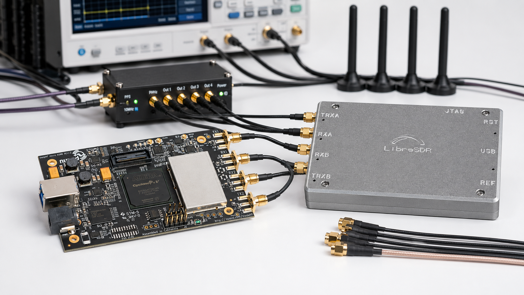
A MIMO testbed is one of the most useful RF research setups a university, telecom lab, 5G/6G team, AI-RAN group, or wireless engineering department can build. It allows researchers to test multiple-input multiple-output communication, beamforming, channel estimation, spatial diversity, multi-antenna sensing, interference mitigation, and real wireless algorithms with controllable RF hardware.
But a good MIMO testbed is not only a 2×2 SDR. The hardware must be chosen around channel count, bandwidth, synchronization, clock distribution, antenna layout, RF safety, calibration, compute, cabling, and measurement tools. A 2×2 teaching lab can be built with a USRP B210 or bladeRF 2.0 micro. A 4×4 research testbed may need USRP N310, X410-class hardware, or multiple synchronized radios. A phase-coherent array needs stricter clocking, triggering, calibration, and antenna geometry than a simple two-channel demo.
This guide explains how to choose MIMO testbed hardware for 2×2, 4×4, synchronization, clocks, antennas, RF test equipment, and university purchase orders.
Browse USRP SDR devices, bladeRF SDR devices, PlutoSDR and PLUTO+ SDR radios, RF test and measurement equipment, and the SDRstore.eu request-a-quote guide.
Quick Answer: What Hardware Do You Need for a MIMO Testbed?
| Testbed layer | Recommended hardware | Why it matters |
|---|---|---|
| Starter 2×2 MIMO | USRP B210, bladeRF 2.0 micro, PLUTO+ SDR | Good for teaching, GNU Radio, private 5G learning, basic beamforming, and two-channel experiments. |
| Advanced 2×2 MIMO | USRP X310 or higher-end USRP platform | Better bandwidth, FPGA resources, external timing, and networked SDR workflows. |
| 4×4 MIMO | USRP N310, X410-class hardware, or synchronized multi-SDR setup | Provides four RF channels for spatial multiplexing, sensing, direction finding, and multi-antenna research. |
| Clock synchronization | 10 MHz reference, 1 PPS, GPSDO, OctoClock-style distribution, PTP where required | Keeps radios aligned in frequency and time for repeatable measurements. |
| Phase coherence and calibration | Shared LO/reference where possible, calibration signal, couplers, reference antenna, repeatable cables | Needed when phase relationships between channels matter. |
| Antenna array | Matched antennas, stable mounting, known spacing, equal cables | Defines the spatial behavior of the testbed. |
| RF safety and measurement | Attenuators, dummy loads, RF power meter, spectrum analyzer, NanoVNA | Protects radios and validates signal levels, antennas, cables, and test paths. |
| Compute and networking | Strong Linux workstation/server, USB 3.0, 10GbE, 25GbE, or 100GbE depending on radio | High-channel-count SDR creates heavy IQ data streams and real-time processing load. |
The simple rule: for learning, start with 2×2. For serious research, define whether you need time alignment, frequency lock, phase coherence, or full calibration before buying the radio.
2×2 vs 4×4 MIMO: What Is the Difference?
2×2 MIMO means two transmit paths and two receive paths. It is the best starting point for most university labs because it supports many core concepts without making the system too expensive or difficult to debug.
4×4 MIMO means four transmit paths and four receive paths, or at least four coherent receive paths depending on the research goal. It is more useful for spatial multiplexing, direction finding, beamforming, multi-user MIMO, channel sounding, and ISAC research, but it requires stricter synchronization and more careful RF design.
| Feature | 2×2 MIMO | 4×4 MIMO |
|---|---|---|
| Cost | Lower | Higher |
| Complexity | Good for first MIMO lab | Requires more planning and calibration |
| Typical hardware | USRP B210, bladeRF 2.0 micro, PLUTO+, USRP X310 | USRP N310, X410-class SDR, multiple synchronized radios |
| Best use | Teaching, private 5G, two-channel beamforming, basic MIMO | Advanced MIMO, array processing, ISAC, channel sounding, direction finding |
| Clocking requirement | Moderate if both channels are in one SDR | Strict, especially if using multiple devices |
| Calibration effort | Lower | Higher |
Best 2×2 MIMO SDR Hardware
USRP B210: Best starter 2×2 MIMO SDR for research labs
The USRP B210 is one of the best starter choices for a 2×2 MIMO SDR testbed. It is widely used in universities, GNU Radio workflows, srsRAN, OpenAirInterface, Open5GS, private 5G labs, and wireless research.
Choose USRP B210 when the lab needs:
- 2×2 MIMO with one compact SDR
- UHD and GNU Radio support
- Private 5G or OAI/srsRAN experiments
- AI-RAN and neural receiver starter testbeds
- Teaching labs where one radio per bench is practical
- Lower-cost research before upgrading to X310 or X410-class hardware
Limitations: B210 is excellent for 2×2 work, but it is not a 4×4 platform. It also depends on a reliable USB 3.0 host and cannot replace higher-end networked SDRs for large multi-radio arrays.
USRP X310: Better for advanced 2×2 MIMO and high bandwidth
The USRP X310 is a stronger 2×2 research platform when the project needs more bandwidth, more FPGA resources, external timing, and 10GbE or PCIe-style workflows.
Choose USRP X310 when the lab needs:
- Higher-bandwidth MIMO experiments
- External 10 MHz and PPS timing
- Networked SDR streaming
- Advanced GNU Radio and UHD work
- Channel sounding and real-time DSP research
- Long-term university research infrastructure
Read: USRP B210 vs X310: Which SDR Should a Research Lab Buy?.
bladeRF 2.0 micro: Compact 2×2 MIMO with FPGA direction
bladeRF 2.0 micro is a good 2×2 MIMO SDR for developers who want compact hardware, libbladeRF, USB 3.0, FPGA-oriented work, and custom waveform development.
Choose bladeRF 2.0 micro xA4 when most processing will happen on the host PC. Choose bladeRF 2.0 micro xA9 when the project needs more FPGA capacity.
Best for:
- 2×2 MIMO learning
- FPGA-related research
- GNU Radio and SoapySDR workflows
- Compact lab setups
- Custom waveform experiments
Read: bladeRF 2.0 micro xA4 vs xA9.
PLUTO+ SDR: Lower-cost 2T2R experimentation
PLUTO+ SDR is useful when the lab wants AD9363-based 2TX/2RX experimentation, Ethernet connectivity, MicroSD boot support, and lower-cost SDR development.
Choose PLUTO+ when the lab needs:
- Lower-cost 2T2R SDR experiments
- AD9363-based learning
- Ethernet SDR workflows
- GNU Radio or SDRangel experiments
- Teaching labs where USRP cost is too high for every bench
Read: PLUTO+ SDR Review.
Best 4×4 MIMO SDR Hardware
USRP N310: Practical 4-channel networked SDR
USRP N310-class hardware is one of the most practical directions for a 4-channel SDR testbed. It is designed as a networked SDR with four transmit and four receive channels, external synchronization direction, and deployment-friendly management features.
Choose N310-class hardware when the lab needs:
- 4 RX and 4 TX channels in one SDR platform
- Networked SDR operation
- Distributed or multi-node research
- External timing and synchronization
- Higher channel density than B210 or X310
- MIMO, channel sounding, direction finding, or ISAC experiments
For a university purchase order, N310-class hardware is easier to justify when the research specifically needs more than two coherent RF channels.
USRP X410: Premium 4×4 and high-bandwidth research platform
X410-class hardware is a premium direction for labs that need high bandwidth, four independent TX/RX channels, fast networking, and advanced AI-RAN, O-RAN, 6G, ISAC, or channel-sounding workflows.
Choose X410-class hardware when the lab needs:
- 4 TX and 4 RX channels
- Very wide instantaneous bandwidth
- 100GbE or 25GbE-class host connectivity
- Advanced synchronization and internal GPSDO direction
- Real-time AI-RAN or neural receiver work
- High-end 6G and ISAC research
X410-class hardware should be treated as research infrastructure. It needs strong compute, fast networking, timing planning, and a proper RF bench.
Multiple synchronized 2×2 SDRs
Another way to build 4×4 is to synchronize two 2×2 SDRs. This can be useful if the lab already owns multiple USRP B210, X310, bladeRF, or other 2×2 radios.
This approach can work, but it is harder than buying one 4-channel platform because every radio must be aligned in frequency, time, and sometimes phase. You may need:
- Shared 10 MHz reference
- Shared 1 PPS reference
- Timed commands
- Calibration signal
- Equal-length cables
- Stable temperature environment
- Careful software startup order
- Repeated phase and delay calibration
If phase coherence matters, do not assume that two independent SDRs become a coherent 4×4 array just because they share a clock. Test and calibrate the system.
Receive-Only Coherent Arrays: KrakenSDR and Similar Tools
Not every MIMO testbed needs transmit capability. If the project is direction finding, passive radar, TDOA-style experiments, or receive-only coherent monitoring, a multi-channel coherent receiver can be useful.
KrakenSDR is a five-channel coherent-capable RTL-SDR receiver where all channels are clocked from a single local oscillator and managed through synchronization software.
Use KrakenSDR-style hardware for:
- Direction finding
- Passive radar experiments
- Receive-only coherent arrays
- Angle-of-arrival learning
- RF sensing education
Do not use receive-only coherent receivers as a replacement for full 2×2 or 4×4 transmit/receive MIMO platforms.
Synchronization: Time, Frequency, Phase, and Calibration
Synchronization is the most important part of a MIMO testbed. Different experiments require different levels of synchronization.
| Synchronization level | What it means | Typical hardware |
|---|---|---|
| Frequency lock | All radios use the same frequency reference | 10 MHz reference, GPSDO, lab reference clock |
| Time alignment | Samples and timed events start from a known shared time | 1 PPS, timed commands, UHD time sync, trigger lines |
| Phase coherence | Relative phase between channels is stable and known enough for the experiment | Shared LO or coherent architecture, calibration path, stable cabling, reference signal |
| Array calibration | Amplitude, phase, delay, cable, antenna, and RF-chain differences are measured and compensated | Calibration source, couplers, known target, reference antenna, VNA, repeatable geometry |
Many MIMO projects fail because the lab only solves frequency lock and assumes phase coherence. For beamforming, AoA, channel sounding, and ISAC, calibration is usually as important as the radio choice.
Clock Hardware for MIMO Testbeds
10 MHz reference
A 10 MHz reference gives all SDRs a common frequency source. This reduces frequency offset between devices and is the first requirement for multi-device synchronization.
1 PPS reference
A 1 PPS signal provides a shared time reference. It is commonly used to align device time, trigger timed commands, and coordinate sample timing between radios.
GPSDO
A GPSDO is useful when the lab needs a stable timing and frequency reference without relying on another lab instrument. It is common in outdoor, distributed, or standalone testbeds.
Clock distribution
When using multiple radios, use a clock distribution system rather than splitting references with random cables. A distribution unit helps provide consistent levels and stable references to each SDR.
PTP and network timing
PTP becomes relevant in O-RAN, distributed systems, and some networked SDR labs. It is not a replacement for all RF synchronization needs, but it can be part of a serious timing architecture.
Antennas for 2×2 and 4×4 MIMO
A MIMO testbed is only as good as its antennas and geometry. Poor antenna placement can make good SDR hardware look bad.
Antenna checklist
- Use the same antenna model for all MIMO elements where possible.
- Use equal cable lengths for each antenna path.
- Document antenna spacing and orientation.
- Use stable mounts, not loose antennas on a desk.
- Measure cables and antennas with a VNA where possible.
- Keep metal objects and laptops away from the array.
- Repeat calibration when antennas or cables move.
- Use cabled tests before over-the-air tests.
Antenna spacing
A common starting point for many narrowband MIMO and array experiments is around half a wavelength between antenna elements. The correct spacing depends on frequency, array type, research goal, propagation environment, and whether the lab studies diversity, beamforming, AoA, or sensing.
| Frequency | Approximate wavelength | Approximate half-wavelength spacing |
|---|---|---|
| 900 MHz | 33.3 cm | 16.7 cm |
| 1.8 GHz | 16.7 cm | 8.3 cm |
| 2.4 GHz | 12.5 cm | 6.25 cm |
| 3.5 GHz | 8.6 cm | 4.3 cm |
| 5.8 GHz | 5.2 cm | 2.6 cm |
These values are starting points, not universal rules. Real antenna spacing should be selected around the experiment and validated with measurements.
RF Cables, Adapters, and Repeatability
Cables are part of the testbed. In MIMO, unequal cables can create phase and delay differences that appear as algorithm problems.
Cable checklist
- Use equal-length cables for matched MIMO paths.
- Use the same cable type for each channel.
- Label every cable.
- Avoid random adapter chains.
- Keep cables stable during measurements.
- Measure cable loss and phase where possible.
- Document cable serial numbers or labels in experiments.
- Use torque-consistent SMA connections where repeatability matters.
RF Safety Hardware
Transmit-capable MIMO testbeds can damage equipment if connected incorrectly. RF safety accessories are not optional.
Minimum RF safety kit
- Fixed attenuators in multiple values
- 50-ohm dummy loads
- RF power meter
- Short SMA cables
- DC blocks where needed
- Directional couplers where useful
- Shield box or cabled RF path for early tests
- Spectrum analyzer or TinySA Ultra
- NanoVNA for antenna and cable checks
Browse RF power meters, RF dummy loads, and spectrum analyzers.
Compute and Networking for MIMO SDR
MIMO SDR testbeds generate large IQ data streams. The more channels and bandwidth you use, the more important the host computer becomes.
Starter 2×2 compute
- Modern x86 Linux workstation
- 8-core CPU or better
- 32 GB RAM minimum, 64 GB preferred
- NVMe SSD
- Reliable USB 3.0 for B210 or bladeRF
- Good cooling and stable power
Advanced 4×4 compute
- High-performance workstation or server
- 16+ CPU cores
- 64–128 GB RAM
- Fast NVMe storage for IQ capture
- 10GbE, 25GbE, or 100GbE depending on SDR
- Dedicated SDR network interfaces
- Linux tuning for high-rate streaming
- Optional GPU for AI-RAN, neural receiver, or channel-estimation research
For networked radios such as X310, N310, or X410-class hardware, do not use the same network path for SDR streaming, normal internet, monitoring, and file transfers. Separate the SDR data path wherever possible.
Recommended MIMO Testbed Packages
Package 1: Beginner 2×2 MIMO teaching lab
- 1× USRP B210 or bladeRF 2.0 micro per bench
- Linux workstation
- 2–4 matched antennas
- Equal-length SMA cables
- Basic attenuator kit
- Dummy loads
- NanoVNA-H4 for antenna/cable validation
- TinySA Ultra for spectrum checks
Best for: undergraduate wireless labs, GNU Radio teaching, private 5G foundations, basic MIMO, and beamforming demonstrations.
Package 2: Advanced 2×2 research lab
- 1× USRP X310 or high-end 2-channel SDR
- Strong Linux workstation
- 10GbE NIC and suitable cable
- External 10 MHz and PPS reference
- Matched antennas and stable array mount
- RF power meter
- Attenuators, dummy loads, couplers, and filters
- GNU Radio, UHD, OAI, srsRAN, or custom software stack
Best for: serious 2×2 MIMO, channel sounding, O-RAN/AI-RAN foundations, and repeatable wireless research.
Package 3: 4×4 MIMO research lab
- USRP N310, X410-class hardware, or synchronized multi-radio setup
- High-performance server with 10GbE/25GbE/100GbE as required
- 10 MHz and 1 PPS timing architecture
- Clock distribution hardware
- 4 matched antennas
- Stable 4-element array mount
- Equal-length RF cables
- Calibration source or reference signal path
- RF power meter, TinySA Ultra, NanoVNA, attenuators, dummy loads, and couplers
Best for: advanced MIMO, beamforming, multi-user MIMO, ISAC, direction finding, channel sounding, and 6G research.
Package 4: Receive-only coherent array
- KrakenSDR or similar coherent multi-channel receiver
- Raspberry Pi or Linux host
- 5 matched antennas
- Stable array mount
- Known geometry and calibration workflow
- GPS or mapping tools where direction finding is in scope
Best for: direction finding, passive radar, receive-only sensing, and coherent receiver education.
MIMO Testbed Calibration Checklist
- Record SDR model, serial number, firmware, FPGA image, and driver version.
- Record sample rate, center frequency, bandwidth, gain, and clock source.
- Use the same 10 MHz reference and PPS where required.
- Use timed commands for synchronized start where supported.
- Measure or document cable lengths.
- Measure antenna match with NanoVNA.
- Check transmit power with RF power meter.
- Check spectrum with TinySA Ultra or spectrum analyzer.
- Run a known calibration signal before real experiments.
- Repeat calibration when cables, antennas, temperature, gain, or frequency changes.
Best Hardware by Research Goal
| Research goal | Recommended hardware | Notes |
|---|---|---|
| 2×2 MIMO teaching | USRP B210 or bladeRF 2.0 micro | Best balance of cost, channel count, and software support. |
| Private 5G MIMO | USRP B210 first, X310 for advanced work | Use srsRAN or OpenAirInterface with safe RF path. |
| 4×4 channel sounding | N310, X410-class hardware, or synchronized X310 setup | Plan clocking, calibration, and storage before buying. |
| Beamforming research | 4-channel SDR or synchronized radios | Phase calibration and antenna geometry are critical. |
| ISAC research | X310/X410-class SDR, stable clocks, controlled targets | Requires repeatable timing, waveform control, and measurement tools. |
| AI-RAN neural receiver | B210 for starter, X310/X410-class for advanced | Add GPU compute and dataset logging. |
| Receive-only direction finding | KrakenSDR or coherent receiver array | Good for AoA and passive sensing, not transmit MIMO. |
Common MIMO Hardware Mistakes
Buying two SDRs and assuming they are coherent
Multiple SDRs need shared references, timed starts, and calibration. Coherence is a system property, not just a shopping-cart item.
Ignoring cables
Unequal or unstable cables can create phase and delay errors that look like algorithm problems.
Using loose antennas on a desk
Antenna geometry matters. Use a stable mount and document spacing, height, orientation, and environment.
Skipping RF power checks
Before connecting TX to RX, calculate attenuation and confirm signal levels with a power meter.
Trying 4×4 before 2×2 works
Build and debug a stable 2×2 workflow first. Then scale to 4×4.
Using OTA testing too early
Start with cabled RF paths and controlled levels. Move to over-the-air only when legal, safe, and required by the experiment.
Legal and RF Safety Notes
MIMO testbeds often use transmit-capable SDRs. Use them only in legal, authorized, and controlled lab conditions.
- Do not transmit in licensed bands without authorization.
- Use dummy loads and cabled RF paths when radiation is not required.
- Use attenuators before connecting transmitters to receivers.
- Verify maximum input levels for SDRs and instruments.
- Use shielding where required.
- Document frequency, bandwidth, gain, power level, antennas, and RF path.
- Do not use experimental SDR setups for safety-of-life decisions.
Purchase-Order Justification Examples
USRP B210 2×2 MIMO justification
USRP B210 is required as a UHD-compatible 2×2 MIMO SDR platform for teaching and research in wireless communications, private 5G, GNU Radio, OpenAirInterface, srsRAN, MIMO channel estimation, and AI-RAN dataset collection.
USRP X310 advanced MIMO justification
USRP X310 is required for higher-bandwidth 2×2 MIMO research, external synchronization, networked SDR streaming, FPGA-based signal processing, and repeatable wireless experiments beyond the capability of USB-based SDR hardware.
4×4 MIMO platform justification
A 4-channel SDR platform is required because the research includes multi-antenna channel sounding, beamforming, direction finding, spatial multiplexing, or ISAC experiments that cannot be performed with a 2-channel radio.
Clock and synchronization justification
External clock and synchronization hardware is required to provide common 10 MHz and PPS references across MIMO radios, enabling repeatable timing, frequency stability, and calibrated multi-channel measurements.
Antenna array justification
Matched antennas, equal-length cables, and stable antenna mounts are required to create a repeatable MIMO array geometry for beamforming, channel estimation, sensing, and spatial-processing experiments.
Request a Quote for MIMO Testbed Hardware
Universities, telecom labs, RF research groups, AI-RAN teams, 6G projects, cybersecurity labs, and engineering departments can request a formal quotation directly from SDRstore.eu.
Use the Add to Quote button on product pages or the document icon on product cards. Add SDRs, USRP devices, bladeRF, PLUTO+, antennas, cables, attenuators, dummy loads, TinySA Ultra, NanoVNA, RF power meters, clocking accessories, filters, and project notes to one quote request.
A quote request is useful when you need:
- A 2×2 MIMO teaching lab
- A 4×4 MIMO research testbed
- USRP B210, X310, N310, or X410-class hardware alternatives
- Matched antennas and RF accessories
- RF safety accessories in one offer
- Formal pricing for university or company purchasing
- A phased MIMO lab rollout
Read the SDRstore.eu quote-request guide.
Related SDRstore.eu Guides
- 2×2 MIMO SDR Explained: USRP B210, PLUTO+, bladeRF, LimeSDR, and Research Use Cases
- USRP B210 vs X310: Which SDR Should a Research Lab Buy?
- USRP B210 for srsRAN and OpenAirInterface
- bladeRF 2.0 micro vs USRP B210
- PLUTO+ SDR Review: AD9363 2T2R SDR Transceiver
- O-RAN Research Lab Hardware
- AI-RAN Explained
- SDR for 6G Research
- Private 5G Lab Hardware Checklist
- SDR Hardware for RF Product Testing
Official and Technical Resources
- Ettus: Synchronization and MIMO Capability with USRP Devices
- UHD Manual: Device Synchronization
- UHD Manual: USRP B200/B210 Series
- Ettus Research USRP N310 official page
- Ettus Research USRP X410 overview
- UHD Manual: USRP X4x0 Series
- Nuand bladeRF 2.0 micro xA4 official page
- Nuand bladeRF clock reference notes
- Analog Devices AD9361 official page
- KrakenSDR official product page
Final Recommendation
For a first MIMO lab, start with a stable 2×2 platform such as USRP B210, bladeRF 2.0 micro, or PLUTO+. Add matched antennas, equal-length cables, attenuators, dummy loads, TinySA Ultra, NanoVNA, and clear measurement procedures.
For advanced 2×2 research, choose USRP X310 or higher-end hardware with external timing and a strong host computer. For 4×4 MIMO, use a 4-channel SDR such as N310/X410-class hardware or multiple radios synchronized with 10 MHz, PPS, timed commands, and calibration.
The best MIMO testbed is not just the radio with the most channels. It is the setup where SDR hardware, clocks, cables, antennas, calibration, compute, and RF safety are designed together from the beginning.
FAQ
What hardware do I need for a 2×2 MIMO testbed?
A 2×2 MIMO testbed needs a 2TX/2RX SDR such as USRP B210, bladeRF 2.0 micro, PLUTO+, or USRP X310, plus a Linux workstation, matched antennas, equal-length cables, attenuators, dummy loads, RF power meter, spectrum analyzer, and NanoVNA.
What hardware do I need for a 4×4 MIMO testbed?
A 4×4 MIMO testbed needs a 4-channel SDR such as USRP N310 or X410-class hardware, or multiple synchronized 2×2 SDRs. It also needs shared clocking, PPS timing, calibration hardware, matched antennas, equal-length cables, and strong compute/networking.
Is USRP B210 good for MIMO research?
Yes. USRP B210 is a strong starter 2×2 MIMO SDR for teaching, GNU Radio, private 5G, OpenAirInterface, srsRAN, AI-RAN learning, and wireless research.
Is USRP X310 better than B210 for MIMO?
USRP X310 is better for advanced MIMO research when higher bandwidth, 10GbE networking, external timing, FPGA resources, and long-term research infrastructure matter. B210 is better for lower-cost starter 2×2 labs.
Can I build 4×4 MIMO with two 2×2 SDRs?
Yes, but it requires shared references, timed starts, calibration, stable cabling, and careful software control. Two independent SDRs are not automatically phase-coherent just because they are connected to the same computer.
What clock signals are needed for synchronized SDR MIMO?
The common starting point is a shared 10 MHz reference for frequency lock and a shared 1 PPS signal for time alignment. Some experiments also require shared LO, trigger lines, PTP, GPSDO, or calibration signals.
Do MIMO antennas need equal cable lengths?
Equal cable lengths are strongly recommended because cable delay and phase differences affect MIMO measurements. For serious research, label and measure every cable and repeat calibration after changes.
What antenna spacing should I use for a MIMO testbed?
A common starting point is around half a wavelength between antenna elements. The best spacing depends on frequency, array type, propagation environment, and whether the research focuses on diversity, beamforming, AoA, or sensing.
Do I need a NanoVNA for MIMO experiments?
Yes, it is strongly recommended. A NanoVNA helps validate antennas, cables, filters, return loss, impedance, and matching before the lab blames algorithm or SDR issues.
Can SDRstore.eu quote a complete MIMO testbed?
Yes. Use the Add to Quote button on product pages or the document icon on product cards. Add SDRs, antennas, cables, clocks, attenuators, dummy loads, RF tools, and project notes so the complete MIMO setup can be quoted together.
No posts found
Write a review
We support all major card and digital payment options. More local methods are available and shown during checkout.
You enter into a binding sales contract once you have received an 'order confirmation and sales receipt' email from us, in line with our Sales & Delivery conditions. Therefore, sdrstore.eu has the right to cancel your order in the event of technical problems, delivery failure, Fair use policy and other similar situations.
Your payments are protected by advanced encryption and 3-D Secure authentication for safe online shopping.