





dBm to Watts Explained: RF Power Conversion Table and Calculator
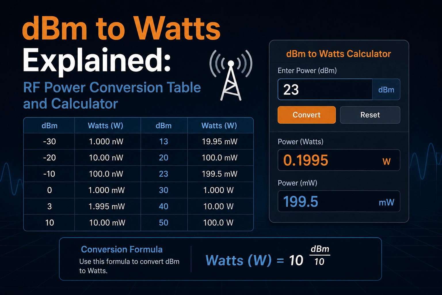
dBm is one of the most common units in radio-frequency engineering, but it can be confusing when RF equipment is also specified in milliwatts or watts. A transmitter may be rated at 30 dBm, an SDR input may have a safe limit expressed in dBm, an RF power meter may display -20 dBm, while an amplifier may be advertised as 5 W.
Fortunately, dBm to watts conversion follows a simple logarithmic relationship. The most important reference point is:
0 dBm = 1 milliwatt = 0.001 watt
From there, every increase of 10 dB multiplies power by 10. That means 10 dBm is 10 mW, 20 dBm is 100 mW, 30 dBm is 1 W, 40 dBm is 10 W, and 50 dBm is 100 W.
This guide includes a dBm to watts calculator, watts to dBm calculator, conversion formulas, common RF power tables, practical SDR and transmitter examples, dBm vs dB vs dBW explanations, 50-ohm voltage examples, and safe RF measurement advice.
Browse RF power meters, RF dummy loads, RF test and measurement equipment, software-defined radio hardware, and request a formal RF equipment quote from SDRstore.eu.
dBm to Watts Calculator
Enter a value below to convert dBm to watts, milliwatts, microwatts, nanowatts, and picowatts. You can also convert watts back to dBm.
Quick dBm to Watts Conversion Table
| dBm | Watts | Common unit |
|---|---|---|
| -120 dBm | 0.000000000000001 W | 1 fW |
| -110 dBm | 0.00000000000001 W | 10 fW |
| -100 dBm | 0.0000000000001 W | 0.1 pW |
| -90 dBm | 0.000000000001 W | 1 pW |
| -80 dBm | 0.00000000001 W | 10 pW |
| -70 dBm | 0.0000000001 W | 100 pW / 0.1 nW |
| -60 dBm | 0.000000001 W | 1 nW |
| -50 dBm | 0.00000001 W | 10 nW |
| -40 dBm | 0.0000001 W | 100 nW / 0.1 µW |
| -30 dBm | 0.000001 W | 1 µW |
| -20 dBm | 0.00001 W | 10 µW |
| -10 dBm | 0.0001 W | 100 µW / 0.1 mW |
| 0 dBm | 0.001 W | 1 mW |
| 10 dBm | 0.01 W | 10 mW |
| 20 dBm | 0.1 W | 100 mW |
| 30 dBm | 1 W | 1 W |
| 40 dBm | 10 W | 10 W |
| 50 dBm | 100 W | 100 W |
| 60 dBm | 1000 W | 1 kW |
The dBm to Watts Formula
To convert dBm to watts:
P(W) = 10^((dBm - 30) / 10)
To convert dBm directly to milliwatts:
P(mW) = 10^(dBm / 10)
Example: 20 dBm to watts
P(W) = 10^((20 - 30) / 10)
P(W) = 10^-1 = 0.1 W
Therefore:
20 dBm = 0.1 W = 100 mW
Example: 30 dBm to watts
P(W) = 10^((30 - 30) / 10)
P(W) = 10^0 = 1 W
Therefore:
30 dBm = 1 W
Example: -60 dBm to watts
P(W) = 10^((-60 - 30) / 10)
P(W) = 10^-9 W
Therefore:
-60 dBm = 1 nW
The Watts to dBm Formula
To convert watts to dBm:
dBm = 10 × log10(P(W)) + 30
If the power is already expressed in milliwatts:
dBm = 10 × log10(P(mW))
Example: 5 watts to dBm
dBm = 10 × log10(5) + 30
dBm ≈ 36.99 dBm
Therefore:
5 W ≈ 37 dBm
Example: 100 watts to dBm
dBm = 10 × log10(100) + 30
dBm = 50 dBm
Therefore:
100 W = 50 dBm
Common dBm Values Used in RF
| dBm | mW | Watts |
|---|---|---|
| 0 dBm | 1 mW | 0.001 W |
| 1 dBm | 1.259 mW | 0.001259 W |
| 2 dBm | 1.585 mW | 0.001585 W |
| 3 dBm | 1.995 mW | 0.001995 W |
| 4 dBm | 2.512 mW | 0.002512 W |
| 5 dBm | 3.162 mW | 0.003162 W |
| 6 dBm | 3.981 mW | 0.003981 W |
| 7 dBm | 5.012 mW | 0.005012 W |
| 8 dBm | 6.310 mW | 0.006310 W |
| 9 dBm | 7.943 mW | 0.007943 W |
| 10 dBm | 10 mW | 0.01 W |
| 13 dBm | 19.95 mW | 0.01995 W |
| 14 dBm | 25.12 mW | 0.02512 W |
| 17 dBm | 50.12 mW | 0.05012 W |
| 20 dBm | 100 mW | 0.1 W |
| 23 dBm | 199.5 mW | 0.1995 W |
| 24 dBm | 251.2 mW | 0.2512 W |
| 27 dBm | 501.2 mW | 0.5012 W |
| 30 dBm | 1000 mW | 1 W |
| 33 dBm | 1995 mW | 1.995 W |
| 36 dBm | 3981 mW | 3.981 W |
| 37 dBm | 5012 mW | 5.012 W |
| 40 dBm | 10000 mW | 10 W |
| 43 dBm | 19950 mW | 19.95 W |
| 46 dBm | 39810 mW | 39.81 W |
| 47 dBm | 50120 mW | 50.12 W |
| 50 dBm | 100000 mW | 100 W |
| 53 dBm | 199500 mW | 199.5 W |
| 57 dBm | 501200 mW | 501.2 W |
| 60 dBm | 1000000 mW | 1000 W |
Easy dBm Rules to Remember
You do not need a calculator for every RF power estimate.
Every +10 dB means 10× the power
| Power | dBm |
|---|---|
| 1 mW | 0 dBm |
| 10 mW | 10 dBm |
| 100 mW | 20 dBm |
| 1 W | 30 dBm |
| 10 W | 40 dBm |
| 100 W | 50 dBm |
| 1 kW | 60 dBm |
Approximately +3 dB doubles power
- 0 dBm = 1 mW
- 3 dBm ≈ 2 mW
- 6 dBm ≈ 4 mW
- 10 dBm = 10 mW
- 13 dBm ≈ 20 mW
- 20 dBm = 100 mW
- 23 dBm ≈ 200 mW
- 27 dBm ≈ 500 mW
- 30 dBm = 1 W
- 33 dBm ≈ 2 W
- 37 dBm ≈ 5 W
- 40 dBm = 10 W
The exact increase for double power is approximately 3.0103 dB, but the 3 dB rule is very useful for quick RF calculations.
-3 dB approximately halves power
If a 1 W or 30 dBm signal passes through a 3 dB attenuator:
30 dBm - 3 dB = 27 dBm
27 dBm is approximately 0.5 W.
What Does dBm Actually Mean?
dBm means decibels relative to one milliwatt.
The “m” is important because it defines the reference power:
0 dBm = 1 mW
Unlike plain dB, dBm represents an absolute power level.
dB vs dBm: They Are Not the Same
| Unit | Meaning | Example |
|---|---|---|
| dBm | Absolute power referenced to 1 mW | 20 dBm = 100 mW. |
| dB | Relative gain or loss | A 20 dB attenuator reduces power by a factor of 100. |
This distinction makes RF link calculations convenient because a gain or loss in dB can be added directly to an absolute power level in dBm.
Example: transmitter plus amplifier
Suppose an SDR produces:
10 dBm
and an amplifier provides:
+20 dB gain
Ignoring losses:
10 dBm + 20 dB = 30 dBm
30 dBm equals 1 W.
Example: transmitter plus attenuator
Suppose a transmitter produces:
30 dBm
and you install a:
40 dB attenuator
The output becomes:
30 dBm - 40 dB = -10 dBm
-10 dBm equals 0.1 mW or 100 µW.
This type of calculation is essential before connecting a transmitter to a sensitive SDR receiver or spectrum analyzer.
Do Not Add Two dBm Power Levels Directly
A common beginner mistake is adding two independent power levels expressed in dBm.
20 dBm + 20 dBm does not equal 40 dBm.
Each 20 dBm source is 100 mW.
If two ideal independent 100 mW powers are combined:
100 mW + 100 mW = 200 mW
200 mW is approximately:
23 dBm
When adding actual powers:
- Convert each dBm value to watts or milliwatts.
- Add the linear power values.
- Convert the total back to dBm.
This is different from adding a gain or loss in dB to a power level in dBm.
dBm vs dBW
dBW is another logarithmic power unit, but its reference is one watt rather than one milliwatt.
The conversion is:
dBW = dBm - 30
dBm = dBW + 30
| Watts | dBm | dBW |
|---|---|---|
| 1 mW | 0 dBm | -30 dBW |
| 100 mW | 20 dBm | -10 dBW |
| 1 W | 30 dBm | 0 dBW |
| 10 W | 40 dBm | 10 dBW |
| 100 W | 50 dBm | 20 dBW |
| 1000 W | 60 dBm | 30 dBW |
Does 50 Ohms Matter When Converting dBm to Watts?
No. Converting dBm to watts does not require knowing impedance.
30 dBm is 1 W whether the system is 50 ohms, 75 ohms, or another impedance.
Impedance matters when converting power into voltage or current.
For a resistive load:
V(RMS) = √(P × R)
Common values in a 50-ohm RF system
| dBm | Power | Approx. voltage RMS into 50 Ω |
|---|---|---|
| 0 dBm | 1 mW | 0.224 V RMS |
| 10 dBm | 10 mW | 0.707 V RMS |
| 20 dBm | 100 mW | 2.236 V RMS |
| 30 dBm | 1 W | 7.071 V RMS |
| 40 dBm | 10 W | 22.36 V RMS |
These voltage values assume the stated RF power is delivered into a matched 50-ohm resistive load.
Why RF Engineers Prefer dBm
RF systems can involve enormous power ranges. A sensitive receiver may work with signals around -100 dBm while a transmitter can output +40 dBm or more.
In watts, those numbers become awkward:
- -100 dBm = 0.0000000000001 W
- 0 dBm = 0.001 W
- 30 dBm = 1 W
- 40 dBm = 10 W
dBm compresses this huge range into numbers that are easier to calculate and compare.
It also makes link budgets simple because gains and losses expressed in dB can be added or subtracted.
Example RF Link Budget
Suppose a transmitter starts at:
20 dBm
The RF chain contains:
- Amplifier gain: +10 dB
- Cable loss: -2 dB
- Attenuator: -20 dB
The final power is:
20 + 10 - 2 - 20 = 8 dBm
8 dBm equals approximately 6.31 mW.
This is much easier than converting every stage into watts and multiplying individual power ratios.
Typical RF Power Levels
The exact power level varies by device, band, hardware revision, gain configuration, and regulation, but these ranges help put dBm into context.
| Power range | Typical interpretation |
|---|---|
| -120 to -90 dBm | Very weak receiver-level signals. |
| -90 to -60 dBm | Common weak-to-moderate received radio signals. |
| -60 to -30 dBm | Strong receiver input levels in many SDR applications. |
| -30 to 0 dBm | Very strong for sensitive receiver inputs; common controlled lab signal levels. |
| 0 to +20 dBm | Signal-generator, SDR TX, module, or low-power transmitter territory depending on hardware. |
| +20 to +30 dBm | 100 mW to 1 W. |
| +30 to +40 dBm | 1 W to 10 W transmitter power. |
| +40 to +50 dBm | 10 W to 100 W high-power RF equipment. |
These ranges are examples rather than safe-input recommendations. Always check the actual maximum input specification of the connected device.
dBm and SDR Receiver Inputs
This is one of the most important practical uses of dBm conversion.
An SDR receiver is designed for weak radio signals. Connecting a transmitter directly to the receiver can overload or permanently damage the front end.
Consider this example:
Transmitter output:
30 dBm = 1 W
Desired receiver input:
-20 dBm = 10 µW
Required reduction:
30 dBm - (-20 dBm) = 50 dB
You therefore need approximately 50 dB of total path loss to reduce the ideal conducted level from 1 W to 10 µW.
That attenuation might include:
- Fixed attenuators
- Variable attenuator
- Directional coupler loss
- Cable loss
- Other known RF path losses
Always include margin and verify the result with a suitable RF power meter before connecting expensive equipment.
Example: 10 W Transmitter to Spectrum Analyzer
A 10 W transmitter produces:
40 dBm
Suppose the analyzer input should remain at or below:
-10 dBm
The required attenuation is:
40 - (-10) = 50 dB
A theoretical 50 dB attenuator chain would reduce:
40 dBm → -10 dBm
However, the attenuator connected closest to the transmitter must also be able to dissipate the input power. A small SMA attenuator is not automatically safe simply because its attenuation value is correct.
Check:
- Attenuator power rating
- Frequency range
- Connector rating
- Continuous vs peak power
- Cooling
- Analyzer maximum safe input
RF Power Meter vs Spectrum Analyzer for dBm Measurements
Both can display signal power in dBm, but their jobs are different.
| Tool | Best use |
|---|---|
| RF power meter | Direct conducted RF power measurement within its specified frequency and power range. |
| Spectrum analyzer | Viewing power distributed across frequency, harmonics, spurs, interference, and signal bandwidth. |
| SDR | IQ capture, decoding, demodulation, and relative signal analysis. |
Browse RF power meters at SDRstore.eu.
Read: What Is a Spectrum Analyzer? Beginner Guide for RF Testing.
Why Dummy Loads Matter
A dummy load provides a controlled RF termination, normally 50 ohms in common radio systems, and absorbs transmitter power instead of radiating it from an antenna.
This makes dummy loads useful for:
- Transmitter power checks
- Amplifier testing
- SWR and power-meter testing
- Bench alignment
- Controlled SDR transmit experiments
- RF product validation
A dummy load also needs the correct frequency range and power rating.
A 1 W transmitter should not be connected to a load designed for only a few milliwatts, and a 100 W transmitter requires a load capable of dissipating substantial heat.
Browse RF dummy loads.
Common dBm Conversion Examples
How many watts is 0 dBm?
0 dBm = 1 mW = 0.001 W.
How many watts is 10 dBm?
10 dBm = 10 mW = 0.01 W.
How many watts is 20 dBm?
20 dBm = 100 mW = 0.1 W.
How many watts is 23 dBm?
23 dBm ≈ 199.5 mW ≈ 0.2 W.
How many watts is 27 dBm?
27 dBm ≈ 501 mW ≈ 0.5 W.
How many watts is 30 dBm?
30 dBm = 1000 mW = 1 W.
How many watts is 33 dBm?
33 dBm ≈ 1.995 W, commonly approximated as 2 W.
How many watts is 37 dBm?
37 dBm ≈ 5.012 W, commonly approximated as 5 W.
How many watts is 40 dBm?
40 dBm = 10 W.
How many watts is 43 dBm?
43 dBm ≈ 19.95 W, commonly approximated as 20 W.
How many watts is 47 dBm?
47 dBm ≈ 50.12 W, commonly approximated as 50 W.
How many watts is 50 dBm?
50 dBm = 100 W.
How many watts is 60 dBm?
60 dBm = 1000 W = 1 kW.
Negative dBm Values Explained
Negative dBm does not mean negative power.
It means the power is below the 1 mW reference level.
| dBm | Power |
|---|---|
| -10 dBm | 0.1 mW |
| -20 dBm | 0.01 mW / 10 µW |
| -30 dBm | 1 µW |
| -40 dBm | 0.1 µW / 100 nW |
| -50 dBm | 10 nW |
| -60 dBm | 1 nW |
| -70 dBm | 0.1 nW |
| -80 dBm | 10 pW |
| -90 dBm | 1 pW |
| -100 dBm | 0.1 pW |
Receiver work routinely involves extremely small powers, which is one reason dBm is much more convenient than watts.
dBm in Receiver Sensitivity
Receiver sensitivity is often expressed in dBm because the signals involved are tiny.
Consider two hypothetical receivers:
- Receiver A sensitivity: -100 dBm
- Receiver B sensitivity: -110 dBm
The difference is 10 dB.
-110 dBm is one-tenth the power of -100 dBm, so Receiver B can theoretically detect a signal ten times weaker under the stated test conditions.
However, sensitivity comparisons are only meaningful when bandwidth, modulation, data rate, required BER/PER or SNR, noise figure, and measurement method are comparable.
dBm in Spectrum Analyzers
Spectrum analyzers usually display signal level in dBm because they may need to show both very weak and comparatively strong RF signals on the same logarithmic scale.
For example:
- A noise floor may appear near -100 dBm.
- A wanted signal may appear around -70 dBm.
- A strong local signal may appear near -20 dBm.
The differences can then be read directly in dB.
Read: What Is a Spectrum Analyzer?.
dBm in Signal Generators
RF signal generators commonly specify output level in dBm because engineers often need precise, repeatable signal levels for receiver testing.
For example, a receiver test may gradually reduce generator power:
-50 dBm
-60 dBm
-70 dBm
-80 dBm
-90 dBm
-100 dBm
The engineer can then determine the signal level where the receiver stops meeting its required performance.
Read: What Is a Signal Generator? RF Signal Generators Explained for Beginners.
dBm in Amplifier Gain Calculations
Suppose an amplifier has 20 dB gain.
If the input is:
-10 dBm
the ideal output is:
-10 dBm + 20 dB = 10 dBm
10 dBm equals 10 mW.
If the amplifier input rises to:
10 dBm
the ideal linear calculation gives:
10 dBm + 20 dB = 30 dBm = 1 W
But real amplifiers cannot increase output indefinitely. Output eventually reaches compression, saturation, thermal, voltage, current, or device limits.
Always check:
- P1dB
- Maximum output power
- Maximum input power
- Frequency range
- Gain flatness
- Harmonics
- Cooling requirements
dBm and Attenuators
Attenuators are particularly easy to calculate when power is expressed in dBm.
| Input | Attenuation | Output |
|---|---|---|
| 20 dBm | 3 dB | 17 dBm |
| 20 dBm | 10 dB | 10 dBm |
| 20 dBm | 20 dB | 0 dBm |
| 20 dBm | 30 dB | -10 dBm |
| 30 dBm | 30 dB | 0 dBm |
| 40 dBm | 50 dB | -10 dBm |
Attenuators can also be combined:
10 dB + 20 dB + 20 dB = 50 dB total attenuation
However, check the power rating of every attenuator in the chain. The first attenuator receives the highest power and therefore normally has the most demanding dissipation requirement.
Common dBm Mistakes
Confusing dBm and dB
dBm is absolute power. dB is a relative ratio.
Thinking negative dBm means negative power
It does not. -30 dBm is a positive physical power of 1 µW.
Adding two dBm transmitters directly
20 dBm + 20 dBm is not 40 dBm. Convert the powers to linear units first.
Assuming 3 dB is exactly double
3 dB is an excellent approximation. Exact doubling is approximately 3.0103 dB.
Assuming watts conversion depends on 50 ohms
dBm to watts conversion does not depend on impedance. Voltage and current conversion do.
Ignoring cable and connector loss
A 30 dBm transmitter does not necessarily deliver 30 dBm at the antenna after cable, connector, filter, and switch losses.
Connecting high power to an SDR or analyzer
Convert and calculate the full path first. Use rated attenuation and verify safe input limits.
RF Power Measurement Safety Checklist
- Convert transmitter power into dBm before calculating the test path.
- Check the maximum input power of every instrument.
- Use external attenuators where required.
- Check attenuator power ratings, not only attenuation values.
- Use a suitable 50-ohm dummy load for transmitter tests.
- Use an RF power meter when the actual output is uncertain.
- Include cable, coupler, adapter, and filter loss in calculations.
- Use a DC block where bias voltage may be present.
- Start with additional attenuation when the power level is uncertain.
- Never assume an SDR or spectrum analyzer can tolerate transmitter output directly.
Recommended RF Power Measurement Setup
A practical conducted RF bench can include:
- RF power meter
- 50-ohm dummy load
- Fixed attenuators
- Variable or step attenuator
- Directional coupler
- Known-good RF cables
- DC block where required
- Spectrum analyzer for harmonics and spectral checks
- SDR for IQ capture and signal analysis
A typical transmitter measurement path might be:
Transmitter
→ rated directional coupler or attenuator
→ RF power meter / spectrum analyzer measurement path
→ rated 50-ohm dummy load
The exact topology depends on transmitter power, frequency, measurement equipment, and required measurement accuracy.
RF Power Conversion for Product Testing
dBm calculations become particularly useful during RF product development.
Engineers may need to compare:
- Firmware TX power settings
- Amplifier gain
- Filter insertion loss
- Cable loss
- Antenna-feed power
- Receiver sensitivity
- Attenuated test paths
- Production variation
Read: SDR Hardware for RF Product Testing: Pre-Compliance, Interference, and Signal Validation.
Recommended SDRstore.eu Hardware Packages
Package 1: Beginner RF power measurement kit
- RF power meter
- Low-power attenuator set
- 50-ohm dummy load
- Short RF cables
- SMA/N-type adapters as required
Best for: learning dBm, measuring signal-generator output, low-power transmitter testing, and basic RF bench work.
Package 2: SDR transmit testing kit
- HackRF Pro, PLUTO+, bladeRF, or USRP
- RF power meter
- Fixed attenuator chain
- Variable attenuator
- Dummy load
- Spectrum analyzer
- DC block
Best for: controlled SDR transmit experiments, GNU Radio projects, RF validation, and safe receiver testing.
Package 3: Higher-power radio test bench
- RF power meter appropriate for the frequency range
- Directional coupler
- High-power attenuator
- High-power dummy load
- Spectrum analyzer
- Rated coax cables and connectors
Best for: amateur radio, service labs, transmitter alignment, RF amplifier testing, and higher-power product development.
Purchase-Order Justification Examples
RF power meter justification
An RF power meter is required to measure conducted transmitter and signal-generator power in dBm and watts, validate attenuator chains, verify amplifier output, and protect sensitive RF test equipment from excessive input levels.
Attenuator kit justification
Fixed and variable RF attenuators are required to reduce known transmitter power by controlled dB values, protect SDR and analyzer inputs, simulate path loss, and create repeatable receiver-sensitivity measurements.
Dummy-load justification
A rated 50-ohm dummy load is required to absorb RF transmitter power without unnecessary radiation and provide a controlled termination for conducted power, SWR, amplifier, and transmitter testing.
Request a Quote for RF Power Measurement Equipment
Universities, RF laboratories, amateur-radio organizations, telecom teams, IoT developers, product-testing groups, cybersecurity labs, and public-sector buyers can request a formal quotation directly from SDRstore.eu.
Use the Add to Quote button on product pages or the document icon on product cards. Add RF power meters, dummy loads, SDRs, spectrum analyzers, NanoVNA/VNA equipment, cables, filters, attenuators, adapters, and project requirements to one quote request.
A quote request is useful for:
- RF power measurement benches
- Transmitter test equipment
- SDR transmit-safety kits
- University RF teaching labs
- RF product-testing setups
- Higher-power dummy loads
- Formal business or public-sector procurement
Read the SDRstore.eu quote-request guide.
Related SDRstore.eu Guides
- What Is a Spectrum Analyzer? Beginner Guide for RF Testing
- What Is a Signal Generator? RF Signal Generators Explained for Beginners
- Spectrum Analyzer vs Oscilloscope: Which Tool Do You Need?
- TinySA Ultra Setup Guide
- TinySA vs Professional Spectrum Analyzer
- SDR Hardware for RF Product Testing
- RF Cybersecurity Lab Equipment Checklist
- RF Cyber Range Hardware
Final Recommendation
The fastest way to understand dBm is to remember three reference points:
- 0 dBm = 1 mW
- 30 dBm = 1 W
- 60 dBm = 1 kW
Then remember that every +10 dB multiplies power by ten and approximately +3 dB doubles power.
Use dBm when working with SDR receivers, spectrum analyzers, signal generators, amplifiers, attenuators, RF power meters, and link budgets because gains and losses become easy to calculate. Convert back to watts when you need to understand actual transmitter power, thermal dissipation, dummy-load ratings, or equipment safety.
Most importantly, never connect RF equipment based only on a rough dBm-to-watts conversion. Check the actual input limit, frequency range, attenuation, power rating, impedance, and complete RF path before connecting a transmitter to a receiver or test instrument.
FAQ
What is dBm?
dBm is an absolute logarithmic power unit referenced to one milliwatt. 0 dBm equals 1 mW.
How do you convert dBm to watts?
Use P(W) = 10^((dBm - 30) / 10). For example, 30 dBm converts to 1 watt.
How do you convert watts to dBm?
Use dBm = 10 × log10(P(W)) + 30. For example, 10 watts converts to 40 dBm.
How many watts is 20 dBm?
20 dBm equals 0.1 watt, or 100 milliwatts.
How many watts is 30 dBm?
30 dBm equals exactly 1 watt.
How many watts is 40 dBm?
40 dBm equals 10 watts.
How many watts is 50 dBm?
50 dBm equals 100 watts.
How many watts is 60 dBm?
60 dBm equals 1000 watts, or 1 kilowatt.
What does -30 dBm mean?
-30 dBm is still positive power. It equals 1 microwatt, or 0.000001 watt.
What is the difference between dB and dBm?
dBm represents an absolute power level referenced to 1 mW. dB represents a relative gain or loss. A 20 dB amplifier can therefore increase a -10 dBm signal to an ideal +10 dBm output.
What is the difference between dBm and dBW?
dBm is referenced to 1 milliwatt, while dBW is referenced to 1 watt. dBW equals dBm minus 30.
Does converting dBm to watts depend on impedance?
No. Power conversion between dBm and watts does not depend on impedance. Impedance becomes necessary when converting the power into voltage or current.
Does +3 dB double RF power?
Approximately. An exact doubling of power is about +3.0103 dB. The +3 dB rule is normally accurate enough for quick RF calculations.
Can I add two dBm values together?
Not when they represent two independent powers. Convert each dBm value to watts or milliwatts, add the linear powers, then convert the result back to dBm. Gains and losses expressed in dB can be added directly to a dBm power level.
Can SDRstore.eu quote RF power measurement equipment?
Yes. Use the Add to Quote button on product pages or the document icon on product cards. Add RF power meters, dummy loads, SDRs, spectrum analyzers, attenuators, cables, adapters, and project notes so the complete RF measurement setup can be quoted together.
No posts found
Write a review






We support all major card and digital payment options. More local methods are available and shown during checkout.
You enter into a binding sales contract once you have received an 'order confirmation and sales receipt' email from us, in line with our Sales & Delivery conditions. Therefore, sdrstore.eu has the right to cancel your order in the event of technical problems, delivery failure, Fair use policy and other similar situations.






Your payments are protected by advanced encryption and 3-D Secure authentication for safe online shopping.