





USRP N310 Setup Guide: UHD, SFP+, Networking, Clocking, and First Signal
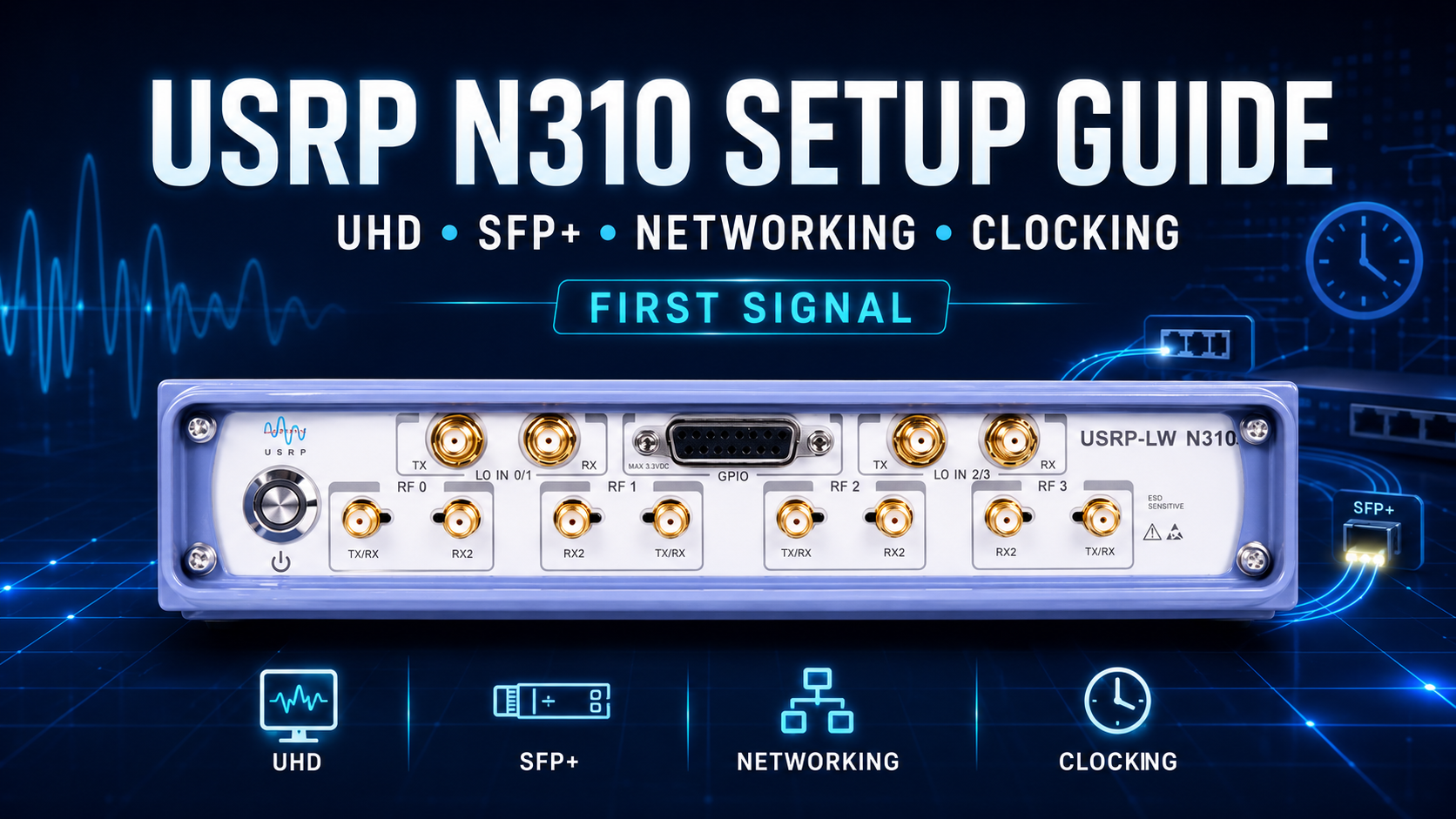
The USRP N310 is very different from a USB SDR such as the USRP B210. You do not simply install a driver, connect one cable, and select the radio in GNU Radio.
The N310 is a four-channel networked SDR with its own embedded Linux system, FPGA image, management network, high-speed SFP+ data interfaces, clock and time sources, GPSDO, and multiple possible Ethernet configurations.
A correct first setup therefore has several layers:
- Install UHD on the host computer.
- Connect to the N310 management interface.
- Verify the N310 filesystem and UHD compatibility.
- Choose the correct FPGA network image.
- Configure the SFP+ data connection.
- Verify device discovery with UHD.
- Choose the clock and time source.
- Test streaming performance.
- Connect an antenna safely.
- Receive the first RF signal.
This guide walks through that complete process using current UHD 4.x workflows and explains the details that commonly cause first-time N310 setups to fail.
Browse the USRP N310 4×4 networked SDR, USRP SDR hardware, and request a formal SDR lab quote from SDRstore.eu.
USRP N310 Setup: Quick Checklist
| Step | Recommended first setup |
|---|---|
| Host OS | Linux is the easiest environment for a first research-lab setup |
| Driver | Current compatible UHD installation |
| Management | Rear RJ45 interface using DHCP |
| High-speed data | SFP1 at 10GbE |
| Host SFP1 IP | 192.168.20.1/24 |
| N310 SFP1 IP | 192.168.20.2/24 |
| 10GbE MTU | 9000 |
| FPGA image | HG for 1GbE SFP0 + 10GbE SFP1; XG for dual 10GbE |
| First clock source | Internal |
| First time source | Internal |
| First RF channel | RF0 / subdevice A:0 |
| First test | uhd_find_devices → uhd_usrp_probe → rx_ascii_art_dft |
For the simplest first successful setup, use the RJ45 port for management and SFP1 for 10GbE sample streaming.
What You Need Before Starting
A practical N310 setup should include:
- USRP N310
- Correct N310 power supply
- Linux workstation
- 10GbE network adapter
- Compatible SFP+ DAC cable or optical SFP+ modules and fiber
- Standard Ethernet connection for management
- Suitable receive antenna
- Current compatible UHD installation
For more advanced work, add:
- External 10 MHz reference
- 1 PPS source
- GPS antenna for the internal GPSDO
- Matched MIMO antennas
- RF attenuators
- Dummy loads
- RF power meter
- Spectrum analyzer
- NanoVNA or laboratory VNA
Important RF Safety Before Powering the N310
The N310 is expensive RF laboratory equipment. Treat the RF inputs accordingly.
Do not connect a transmitter directly into an N310 receiver input.
Ettus documentation warns against applying excessive RF power to the receive inputs and recommends substantial attenuation for direct loopback tests.
For first setup, use a passive receive antenna and an ordinary local broadcast signal.
For conducted TX/RX testing later, use a path such as:
N310 TX
→ suitable fixed attenuation
→ additional attenuation if required
→ N310 RX
Calculate the level before making the connection.
Understand the N310 Architecture First
The N310 contains four TX/RX channels.
Internally, those channels are split across two AD9371 RF transceivers:
AD9371 / Slot A
├── RF0 → A:0
└── RF1 → A:1

AD9371 / Slot B
├── RF2 → B:0
└── RF3 → B:1
The current UHD mapping is:
| Front-panel RF label | UHD subdevice |
|---|---|
| RF0 | A:0 |
| RF1 | A:1 |
| RF2 | B:0 |
| RF3 | B:1 |
This mapping is worth documenting in every lab because it appears repeatedly in UHD, GNU Radio, MIMO scripts and benchmark commands.
Install UHD on the Host Computer
UHD is the USRP Hardware Driver used to discover, configure and stream samples to and from the N310.
As of August 7, 2026, the current official release is UHD 4.10.0.0.
For a new laboratory, use a current supported UHD release unless a specific research stack requires an older version.
After installation, verify UHD:
uhd_config_info --versionYou should see the installed UHD version.
Download Matching UHD Images
Run:
uhd_images_downloaderThis downloads firmware and FPGA images that correspond to the installed UHD version.
For the N3xx filesystem image specifically, UHD also supports:
uhd_images_downloader -t n3xx_common_sdimg_defaultMatching the software stack is important on the N310 because several components interact:
Host UHD
↕
MPM on N310 embedded Linux
↕
FPGA image
↕
AD9371 RF hardware
If those components are significantly mismatched, UHD may report compatibility errors rather than opening the radio.
Do Not Upgrade the Host and Ignore the N310 Image
This is one of the most common N310 mistakes.
Installing a new UHD package on the workstation does not automatically mean that the embedded software currently installed on the N310 matches it.
For a controlled research lab, document:
- Host UHD version
- N310 filesystem artifact/version
- FPGA image
- GNU Radio version
- Research software version
Then treat those versions as one validated laboratory configuration.
Updating the N310 Filesystem
The N310 boots from a microSD card containing its embedded Linux system and MPM software.
Current UHD supports two broad update approaches:
- Writing a complete N3xx SD-card image
- Remote updating through Mender
Download the SD image
uhd_images_downloader -t n3xx_common_sdimg_defaultThe resulting file is normally called:
usrp_n3xx_fs.sdimgWriting the image on Linux
sudo dd if=/path/to/usrp_n3xx_fs.sdimg of=/dev/YOUR_SD_DEVICE bs=1M status=progressBe extremely careful with the output device. Selecting your system SSD instead of the microSD card will overwrite the wrong disk.
Mender Remote Updates
N3xx devices can also update one root-filesystem partition while the other remains bootable.
A typical current UHD 4.x process is:
mender install /path/to/update.mender
reboot
After confirming that the new system works:
mender commitThis dual-partition system is useful in research installations because a failed update does not necessarily leave the radio unbootable.
Connect the Management RJ45 Interface
The rear RJ45 interface is connected to the N310's ARM Linux system.
By default:
RJ45 / eth0 uses DHCP.
Connect it to a network with a DHCP server.
You can then discover the device using:
uhd_find_devicesor current UHD tooling such as:
usrpctl findThe N310 may also advertise a hostname based on its serial number.
SSH Into the N310
Once you know the management IP:
ssh root@N310_MANAGEMENT_IPThe N3xx embedded Linux environment allows you to inspect:
- Network interfaces
- Filesystem version
- MPM
- System logs
- Temperature
- Device configuration
On a newly deployed unit, set a root password instead of leaving unrestricted root access:
passwdThis is particularly important when the radio is connected to a shared university or company network.
Understanding the Three Main Network Interfaces
| Interface | Default | Main role |
|---|---|---|
| RJ45 / eth0 | DHCP | Management, SSH, MPM communication |
| SFP0 / sfp0 | 192.168.10.2/24 | 1GbE or 10GbE depending on FPGA image |
| SFP1 / sfp1 | 192.168.20.2/24 | 10GbE in normal HG/XG configurations |
The important distinction is:
Management traffic and IQ sample streaming do not have to use the same physical interface.
Recommended First Network Architecture
University / lab LAN
        │
        └── RJ45 ─────────── N310 management

Linux workstation
10GbE NIC
        │
        └── SFP+ DAC ─────── N310 SFP1
This keeps management and high-rate sample transport separate.
Configure the Host for SFP1 10GbE
The easiest high-performance first setup is SFP1.
N310 SFP1 default:
192.168.20.2/24Configure the workstation's dedicated 10GbE interface as:
IP address: 192.168.20.1
Subnet:     255.255.255.0
Gateway:    none
MTU:        9000
On Linux using the ip command, a temporary configuration can look like:
sudo ip addr flush dev enp5s0
sudo ip addr add 192.168.20.1/24 dev enp5s0
sudo ip link set dev enp5s0 mtu 9000
sudo ip link set dev enp5s0 up
Replace enp5s0 with the actual 10GbE interface name.
Test SFP+ Connectivity
Connect a compatible 10GbE SFP+ direct-attach cable or supported optical link between the workstation and N310 SFP1.
Then run:
ping 192.168.20.2If this fails, check:
- SFP+ cable/module compatibility
- Host NIC link state
- Host IP address
- Subnet mask
- MTU
- FPGA image
HG vs XG FPGA Image
The FPGA image controls what the two SFP+ interfaces do.
| FPGA image | SFP0 | SFP1 |
|---|---|---|
| HG | 1 Gigabit Ethernet | 10 Gigabit Ethernet |
| XG | 10 Gigabit Ethernet | 10 Gigabit Ethernet |
| HA | 1GbE | Aurora |
| XA | 10GbE | Aurora |
| AA | Aurora | Aurora |
| WX | White Rabbit | 10GbE |
Use HG when:
You want a simple mixed configuration with 1GbE available on SFP0 and 10GbE on SFP1.
Use XG when:
You want both SFP ports available as 10GbE data interfaces.
For most new N310 labs using one 10GbE connection, HG plus SFP1 is perfectly reasonable.
Update the FPGA Image
First update the local image cache:
uhd_images_downloaderThen use the image loader:
uhd_image_loader --args type=n3xx,addr=N310_ADDRESSUse the address or hostname through which the N310 is reachable.
Updating the FPGA causes the FPGA to reload, temporarily taking down the SFP interfaces.
Do not assume a failed ping immediately after an FPGA reload means the device is broken.
Configure Dual 10GbE with XG
For experiments requiring higher aggregate throughput, use the XG image.
Configure two host interfaces:
NIC 1
Host: 192.168.10.1/24
N310 SFP0: 192.168.10.2/24
MTU: 9000
NIC 2
Host: 192.168.20.1/24
N310 SFP1: 192.168.20.2/24
MTU: 9000
Then a UHD device argument can include:
addr=192.168.10.2,second_addr=192.168.20.2Dual-link operation is most useful when streaming multiple wideband channels simultaneously.
Do You Need Dual 10GbE for the First Signal?
No.
For a first FM receiver or low-rate GNU Radio flowgraph, one 10GbE link is more than enough.
Start simple:
SFP1
192.168.20.1 host
192.168.20.2 N310
MTU 9000
Add the second link only when the required aggregate IQ throughput justifies it.
Using SFP0 at 1GbE
The default HG FPGA image makes SFP0 a 1GbE interface.
The traditional getting-started setup uses:
Host: 192.168.10.1
N310: 192.168.10.2
For low-rate streams this can be useful, but it does not provide enough bandwidth for demanding four-channel operation.
For a high-end N310 research system, install 10GbE rather than designing the entire lab around 1GbE.
Find the N310 with UHD
Once network connectivity works:
uhd_find_devicesYou can narrow discovery:
uhd_find_devices --args="type=n3xx"or directly target an address:
uhd_find_devices --args="addr=192.168.20.2"A successful result should identify the device as an N3xx/N310 and report its serial and network details.
Probe the N310
Next run:
uhd_usrp_probe --args="type=n3xx,addr=192.168.20.2"If management runs through a separate RJ45 address, specify it explicitly:
uhd_usrp_probe --args="type=n3xx,mgmt_addr=YOUR_MGMT_IP,addr=192.168.20.2"This is one of the most important diagnostic commands in the entire setup process.
A successful probe verifies:
- UHD communication
- MPM communication
- FPGA compatibility
- RF daughterboards
- Available channels
- Clocking
- Device sensors
N310 Master Clock Rates
The N310 supports three principal master clock rates:
- 122.88 MHz
- 125 MHz
- 153.6 MHz
A device argument can explicitly select one:
master_clock_rate=125e6For example:
type=n3xx,addr=192.168.20.2,master_clock_rate=125e6The desired streaming sample rate must be compatible with the selected master clock and FPGA decimation/interpolation structure.
Choosing a Sample Rate
For a first receive test, do not start with 100 MHz of IQ bandwidth.
Start with something easy such as:
2.5 MS/sor:
5 MS/sThis lets you verify:
- RF tuning
- Gain
- Networking
- GNU Radio configuration
without immediately stressing the host, network and storage system.
Internal Clocking: Best First Setup
For your first signal, use:
clock_source=internal
time_source=internal
This avoids external-reference variables while you verify the rest of the system.
Example:
type=n3xx,addr=192.168.20.2,clock_source=internal,time_source=internalClock Source vs Time Source
These are related but different concepts.
| Setting | Purpose |
|---|---|
| Clock source | Provides the frequency reference |
| Time source | Provides the timing/PPS reference |
For a single basic receiver, internal/internal is sufficient.
For multiple synchronized SDRs, clock and time become critical.
Using an External 10 MHz Reference and PPS
For laboratory synchronization:
clock_source=external
time_source=external
Connect:
- External frequency reference to the rear reference input
- Synchronized PPS to the time/PPS input
External clock and PPS should originate from a properly designed common timing source when several radios must operate together.
Supported External Reference Frequencies
The N3xx hardware supports external frequency-reference options including the standard 10 MHz laboratory reference, with other supported reference frequencies available depending on configuration.
A custom reference-frequency device argument can be supplied where required, for example:
ref_clk_freq=20e6For an ordinary lab, use 10 MHz unless there is a specific reason to do otherwise.
Using the Internal GPSDO
The N310 includes an internal GPS-disciplined timing capability.
Connect a suitable active GPS antenna to the GPS antenna port and place it where the receiver has adequate satellite visibility.
Then use:
clock_source=gpsdo
time_source=gpsdo
GPS lock may not be immediate after startup.
The N310 exposes motherboard sensors including:
gps_lockedgps_timegps_tpvgps_skyref_locked
When Should You Use GPSDO?
GPSDO is useful for:
- Distributed SDR nodes
- Outdoor testbeds
- Long-duration frequency stability
- Systems that need UTC-related timing
- Independent radios at separate locations
It is not required just to receive FM radio with one N310 on a desk.
10 MHz + PPS Does Not Automatically Mean Phase Coherence
This is particularly important for N310 MIMO users.
A shared reference can provide:
- Frequency synchronization
- Sample-time synchronization
but phase-coherent array work can additionally require:
- Known LO relationships
- Timed tuning
- Stable cabling
- Phase calibration
- Known antenna geometry
Read: MIMO Testbed Hardware: 2×2, 4×4, Synchronization, Clocks, and Antennas.
Watch the Rear-Panel LEDs
The rear-panel indicators provide useful diagnostic information.
| LED | Meaning |
|---|---|
| LINK | The N310 has been claimed by a UHD session |
| REF | Reference clock lock indication |
| GPS | GPS lock |
| PPS | Valid PPS activity |
These LEDs can save substantial troubleshooting time when clocking or GPS is not behaving as expected.
Test Network Throughput Before Advanced Experiments
Before building a four-channel MIMO flowgraph, test the host/network path with UHD's benchmark_rate utility.
For a simple single-channel receive test:
benchmark_rate \
  --args "type=n3xx,addr=192.168.20.2,master_clock_rate=125e6" \
  --duration 30 \
  --channels "0" \
  --rx_rate 25e6 \
  --rx_subdev "A:0"
The exact executable path depends on how UHD was installed.
The goal is to reach the desired rate without overruns.
What an Overrun Means
An RX overrun means the radio produced samples faster than the receiving path could reliably consume them.
Possible causes include:
- Network throughput
- Incorrect MTU
- Weak CPU performance
- Busy CPU scheduler
- Slow application processing
- Packet loss
- NIC problems
- Storage that cannot keep up with recording
Do not immediately assume the N310 RF hardware is defective.
Recommended 10GbE Host Configuration
For demanding N310 work, use:
- Dedicated 10GbE NIC
- Direct SFP+ connection where practical
- MTU 9000
- Modern multi-core CPU
- NVMe SSD for large IQ recording
- Separate normal internet/LAN NIC
Avoid routing N310 sample traffic through a normal office network unless that network was specifically designed for sustained SDR traffic.
Receive Your First Signal from the Command Line
Ettus provides the rx_ascii_art_dft example specifically for a quick live spectrum test.
Connect a suitable receive antenna to RF0.
Then use a known strong local signal, such as an FM broadcast station.
Example:
rx_ascii_art_dft \
  --args "type=n3xx,addr=192.168.20.2,master_clock_rate=125e6" \
  --freq 100e6 \
  --rate 2.5e6 \
  --gain 30 \
  --ant RX2 \
  --subdev "A:0" \
  --ref-lvl="-40" \
  --dyn-rng 80
Replace 100e6 with the frequency of a strong local station.
If your management interface is separate:
--args "type=n3xx,mgmt_addr=YOUR_MGMT_IP,addr=192.168.20.2,master_clock_rate=125e6"You should see a live ASCII spectrum centered on the selected frequency.
That confirms:
- UHD works.
- The N310 opens correctly.
- SFP+ streaming works.
- RF0/A:0 works.
- The receiver tunes correctly.
First Signal in GNU Radio
Once the UHD command-line test works, move to GNU Radio.
Create a simple flowgraph:
UHD: USRP Source
        ↓
Frequency Xlating / channel filter if required
        ↓
WBFM Receive
        ↓
Audio Sink
For a basic spectrum-only test:
UHD: USRP Source
        ↓
QT GUI Frequency Sink
GNU Radio USRP Source Settings
A useful first configuration is:
| Setting | Example |
|---|---|
| Device address | type=n3xx,addr=192.168.20.2 |
| Clock source | internal |
| Time source | internal |
| Channel | 0 |
| Subdevice | A:0 |
| Sample rate | 2.5e6 |
| Center frequency | Local FM station |
| Gain | Start moderate and adjust |
Do not begin with all four channels.
Get RF0 working first, then add channels one at a time.
Using All Four N310 Channels
The full current subdevice specification is:
A:0 A:1 B:0 B:1That corresponds to:
Channel 0 → RF0
Channel 1 → RF1
Channel 2 → RF2
Channel 3 → RF3
For a four-channel GNU Radio or UHD application, configure the channels and subdevices explicitly rather than relying on assumptions about ordering.
Why N310 Initialization Sometimes Takes a While
When a UHD session initializes the N310, the platform performs operations including:
- Clock initialization
- JESD link training
- AD9371 initialization
- RF calibration
- Multi-chip synchronization
The N310 can reuse initialization state when appropriate, which makes later sessions faster.
Changing major settings such as:
- Master clock rate
- Clock source
- Calibration configuration
can trigger a full slower reinitialization.
Do not assume the radio is frozen simply because opening it takes longer after changing major clock settings.
Common Problem: uhd_find_devices Finds Nothing
Check the problem in this order:
- Does the management RJ45 have link?
- Can you ping the management IP?
- Can you ping the SFP address?
- Is the host on the correct subnet?
- Is the correct FPGA image loaded?
- Is a firewall blocking discovery/RPC?
- Can you target the address explicitly?
Try:
uhd_find_devices --args="type=n3xx,addr=192.168.20.2"Common Problem: Ping Works but UHD Does Not
This often indicates that layer-3 networking works but the UHD/MPM environment does not.
Check:
- Host UHD version
- N310 filesystem version
- FPGA compatibility
- MPM status
- Firewall/RPC ports
Run:
uhd_usrp_probe --args="type=n3xx,addr=192.168.20.2"The error message usually provides the next clue.
Common Problem: SFP0 Will Not Link at 10GbE
Check the FPGA image.
With the default HG image:
SFP0 = 1GbE
SFP1 = 10GbE
If you need 10GbE on SFP0, load XG.
This is one of the most common N310 configuration misunderstandings.
Common Problem: SFP1 Pings but Streaming Fails
Check the MTU on both ends.
For 10GbE, use:
MTU 9000Verify the Linux interface:
ip link show enp5s0You should see the configured MTU.
Then run benchmark_rate before debugging GNU Radio.
Common Problem: Overflow or Dropped Samples
Reduce the sample rate first.
For example, if 100 MS/s fails, test:
10 MS/s
25 MS/s
50 MS/s
If low rates work but high rates fail, investigate:
- NIC performance
- IRQ placement
- CPU load
- MTU
- Cabling
- Application DSP load
Common Problem: GPS Does Not Lock
Check:
- GPS antenna is connected.
- Antenna has clear enough sky visibility.
- GPS is enabled.
- The device has had sufficient acquisition time.
Use the GPS sensor information rather than assuming that a connected antenna means the GPSDO is locked.
Common Problem: External Reference Does Not Lock
Confirm:
- Reference frequency is correct.
- Signal level meets N310 requirements.
- Correct connector is used.
clock_source=externalis selected.ref_lockedis true.
The REF LED is also useful during troubleshooting.
When to Use the XG FPGA Image
Use XG when the experiment requires:
- Two 10GbE connections
- Several high-bandwidth channels
- Large simultaneous RX/TX data streams
- 4×4 MIMO at demanding sample rates
For one narrowband receiver, XG provides no practical advantage over simply using SFP1 with HG.
When to Use White Rabbit
The N3xx can operate as a White Rabbit slave using an appropriate FPGA image.
This is an advanced timing workflow useful for:
- Distributed research infrastructure
- Precision network-based timing
- Large experimental facilities
It is not required for ordinary N310 GNU Radio operation.
Get the radio working with internal timing before introducing White Rabbit.
First 4×4 MIMO Setup
After individual channels work, move to four-channel testing.
A basic 4×4 research setup can include:
- 1 × N310
- 4 matched antennas
- Equal-length RF cables
- Dedicated 10GbE or dual 10GbE data path
- External timing where required
- Calibration signal
- RF power meter
- Spectrum analyzer
- VNA
Do not start MIMO development until each individual channel has been tested separately.
Network Layout for a Permanent N310 Lab
                    ┌──────────── Lab LAN
                    │
                Management
                    │
                 RJ45
                    │
               ┌────┴────┐
               │  N310   │
               └────┬────┘
                    │ SFP+
                    │ 10GbE
                    │
             Dedicated SDR NIC
                    │
             Linux workstation
                    │
              NVMe / GPU / DSP
For dual 10GbE:
N310 SFP0 ───────── 10GbE NIC 1
N310 SFP1 ───────── 10GbE NIC 2
Avoid mixing high-rate IQ data with normal corporate LAN traffic if possible.
Document Every N310 in a Shared Lab
Record:
- Asset number
- Serial number
- Management IP
- SFP0 IP
- SFP1 IP
- FPGA image
- Filesystem version
- UHD version
- Clock source
- Assigned workstation
This becomes extremely valuable once the laboratory owns several networked USRPs.
N310 for GNU Radio Research
The N310 is particularly useful when GNU Radio projects require:
- Four RF channels
- Network streaming
- External synchronization
- MIMO
- Beamforming
- Channel sounding
- RFNoC development
Read: Best SDR for GNU Radio Projects.
N310 for MIMO Research
The four-channel architecture makes N310 attractive for:
- 4×4 MIMO
- Beamforming
- Multi-user MIMO
- Channel sounding
- Direction finding research
- ISAC experiments
Remember that synchronization and calibration are part of the testbed, not optional details added after the radio works.
Read: MIMO Testbed Hardware.
N310 for Private 5G and Advanced Telecom Labs
N310 can also be useful as part of advanced networked wireless research where four RF channels, external timing and distributed deployment matter.
However, software compatibility should be verified against the exact version of the RAN stack before purchasing hardware for one specific private 5G application.
Read: Private 5G Lab Hardware Checklist.
Recommended N310 Starter Lab Package
- USRP N310
- 10GbE Linux workstation
- Compatible SFP+ DAC cable
- Separate Ethernet management connection
- 4 matched antennas if MIMO is planned
- Equal-length RF cables
- Attenuator set
- 50-ohm dummy loads
- RF power meter
- Spectrum analyzer
- NanoVNA or laboratory VNA
Best for: university research, 4×4 MIMO, GNU Radio, channel sounding, beamforming, RFNoC and advanced wireless development.
Purchase-Order Justification Examples
USRP N310 justification
USRP N310 is required as a four-channel networked software-defined radio platform for GNU Radio, UHD, 4×4 MIMO, beamforming, channel sounding, multi-channel wireless research, distributed SDR deployment, external synchronization and FPGA/RFNoC development.
10GbE networking justification
A dedicated 10 Gigabit Ethernet interface and SFP+ connection are required to transport high-rate complex IQ data between the USRP N310 and research workstation without the throughput limitations of standard Gigabit Ethernet.
Clocking justification
External 10 MHz and PPS timing equipment is required to provide common frequency and time references for repeatable synchronized SDR experiments, multi-device measurements and MIMO research.
RF measurement accessories justification
RF attenuators, dummy loads, RF power meters, spectrum analyzers, VNA equipment and known-good cables are required to protect N310 RF inputs and create repeatable, measurable and safe laboratory signal paths.
Request a Quote for a USRP N310 Research Lab
Universities, research institutes, telecom teams, MIMO laboratories, wireless engineering groups, cybersecurity labs and public-sector organizations can request a formal quotation directly from SDRstore.eu.
Use the Add to Quote button on product pages or the document icon on product cards. Add the N310, networking accessories, antennas, clocking equipment, RF cables, attenuators, dummy loads, RF power meters, spectrum analyzers, NanoVNA/VNA equipment and project requirements to one request.
A quote request is useful for:
- 4×4 MIMO testbeds
- Networked GNU Radio laboratories
- University research grants
- Channel-sounding systems
- Private wireless research
- Multiple synchronized N310 nodes
- Formal company or public-sector procurement
Read: How to Choose SDR Hardware for a Research Grant or University Purchase Order.
Related SDRstore.eu Guides
- MIMO Testbed Hardware: 2×2, 4×4, Synchronization, Clocks, and Antennas
- How to Build a University SDR Lab
- Best SDR for GNU Radio Projects
- Private 5G Lab Hardware Checklist
- O-RAN Research Lab Hardware
- How to Choose SDR Hardware for a Research Grant or University Purchase Order
Official Technical Resources
- Ettus Research USRP N310
- Ettus N300/N310 Getting Started Guide
- Current UHD N3xx Device Manual
- Official UHD Repository
- UHD Releases
- UHD Firmware and FPGA Images
- UHD Device Identification
- UHD Example Programs
- GNU Radio
Final Setup Checklist
Before calling the N310 installation complete, verify all of the following:
uhd_config_info --versionreports the expected UHD version.- The N310 filesystem and FPGA are compatible with the host environment.
- Management RJ45 access works.
- SFP1 responds at 192.168.20.2.
- The 10GbE host NIC uses 192.168.20.1/24.
- MTU is configured correctly.
uhd_find_devicesdiscovers the radio.uhd_usrp_probecompletes successfully.- RF0 maps to A:0.
- Internal clock/time works before external clocking is introduced.
benchmark_rateworks at the sample rate required by the project.- A known local RF signal can be received.
- The GNU Radio USRP Source opens without network or compatibility errors.
Final Recommendation
For the first N310 setup, keep the architecture simple.
Use the rear RJ45 port for management, use SFP1 as a dedicated 10GbE data link, configure the workstation as 192.168.20.1/24 with MTU 9000, leave clock and time sources set to internal, and test only RF0/A:0 at a modest sample rate.
Run uhd_find_devices, then uhd_usrp_probe, then a low-rate rx_ascii_art_dft receive test. Only after those steps work should you introduce GNU Radio, external references, GPSDO, additional channels, dual 10GbE, 4×4 MIMO or RFNoC.
Most difficult N310 problems become much easier to diagnose when networking, UHD compatibility, clocking and RF channels are validated separately instead of configuring everything at once.
FAQ
What UHD version does USRP N310 require?
The N310 has been supported since UHD 3.11, but new installations should normally use a current compatible UHD release unless the research software stack requires a particular older version. As of August 7, 2026, the latest official UHD release is 4.10.0.0.
What is the default N310 SFP0 IP address?
The default SFP0 address is 192.168.10.2/24.
What is the default N310 SFP1 IP address?
The default SFP1 address is 192.168.20.2/24.
What IP should I use on the host for N310 SFP1?
A standard direct 10GbE setup uses 192.168.20.1/24 on the workstation and 192.168.20.2/24 on N310 SFP1.
What MTU should I use for N310 10GbE?
Ettus' N310 10GbE setup guidance uses an MTU of 9000. The host and device network configuration must be compatible to avoid streaming problems.
What is the difference between N310 HG and XG FPGA images?
HG configures SFP0 as 1GbE and SFP1 as 10GbE. XG configures both SFP0 and SFP1 as 10GbE.
Do I need two 10GbE cables for USRP N310?
No. One 10GbE connection through SFP1 is sufficient for many experiments and is ideal for initial setup. Dual 10GbE becomes useful for high aggregate throughput across multiple wideband channels.
How do I check whether UHD sees the N310?
Run uhd_find_devices followed by uhd_usrp_probe. You can also provide the N310 address explicitly using device arguments.
What is RF0 on N310 in UHD?
RF0 maps to subdevice A:0. RF1 maps to A:1, RF2 to B:0 and RF3 to B:1.
What master clock rates does N310 support?
The N310 supports master clock rates of 122.88 MHz, 125 MHz and 153.6 MHz.
Does USRP N310 have a GPSDO?
Yes. The N310 architecture includes an internal GPS-disciplined timing capability and exposes GPS status and time through UHD sensors. A suitable GPS antenna is required for satellite reception.
Should I use internal or GPSDO clocking for the first setup?
Use internal clock and internal time for the first successful receive test. Configure GPSDO or external clocking only after basic networking and UHD communication are confirmed.
Can I use an external 10 MHz reference with N310?
Yes. N310 supports an external frequency reference and PPS timing input for synchronized laboratory setups.
Can N310 work with GNU Radio?
Yes. GNU Radio integrates with USRP hardware through UHD. Configure a UHD USRP Source or Sink with the N310 device address, channel, subdevice, sample rate, center frequency, gain and clocking options.
Why does N310 take a long time to initialize?
A full initialization can include clock setup, JESD link training, AD9371 initialization, RF calibrations and multi-chip synchronization. Changing major clock or calibration settings can trigger a slower full reinitialization.
Why can I ping the N310 but uhd_usrp_probe fails?
Ping only confirms IP connectivity. UHD may still fail because of host/device UHD incompatibility, an incorrect FPGA image, MPM problems, blocked RPC traffic or incorrect device arguments.
Can SDRstore.eu quote a complete N310 research setup?
Yes. Use the Add to Quote button on the N310 product page or the document icon on product cards and include networking, clocking, antennas, RF cables, attenuators, dummy loads and test equipment required by the project.
No posts found
Write a review






We support all major card and digital payment options. More local methods are available and shown during checkout.
You enter into a binding sales contract once you have received an 'order confirmation and sales receipt' email from us, in line with our Sales & Delivery conditions. Therefore, sdrstore.eu has the right to cancel your order in the event of technical problems, delivery failure, Fair use policy and other similar situations.






Your payments are protected by advanced encryption and 3-D Secure authentication for safe online shopping.