





S11 vs S21: S-Parameters Explained for RF Beginners
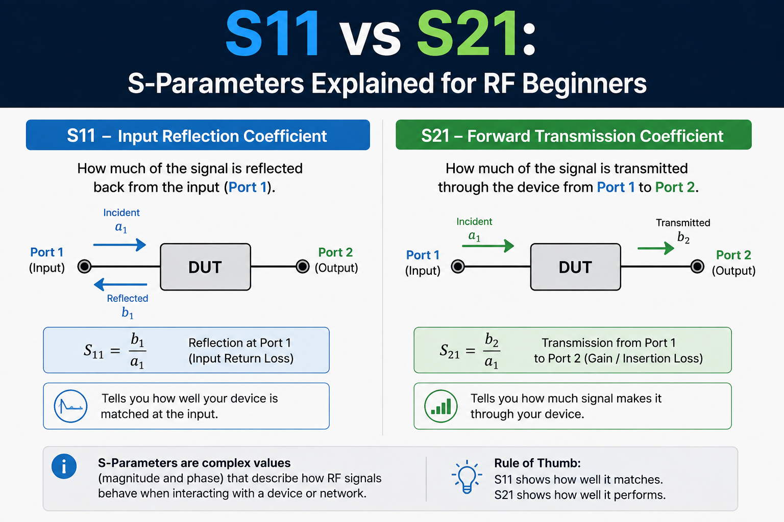
S11 and S21 are two of the most important measurements you will see on a vector network analyzer, NanoVNA, LibreVNA, or professional RF VNA.
The names initially look abstract, but the basic idea is simple:
- S11 tells you what comes back.
- S21 tells you what gets through.
Use S11 when testing an antenna, impedance match, return loss, SWR, or the input of an RF component. Use S21 when testing how much signal passes through a filter, cable, attenuator, amplifier, coupler, or other two-port device.
The difficulty is that S-parameters are normally displayed in decibels, and negative numbers mean different things depending on what you are measuring. An antenna showing S11 = -20 dB is generally a good result. A cable showing S21 = -20 dB would normally indicate a very large loss.
This guide explains S11 vs S21 from the beginning, including reflection, transmission, return loss, insertion loss, SWR, Smith charts, S12, S22, calibration, filters, antennas, cables, amplifiers, and how to interpret common VNA measurements correctly.
Browse VNAs and RF analysis tools, NanoVNA-F V3, and request a formal RF lab quote from SDRstore.eu.
S11 vs S21: Quick Answer
| Measurement | S11 | S21 |
|---|---|---|
| Type | Reflection | Forward transmission |
| Basic question | How much comes back? | How much gets through? |
| Typical VNA path | Port 1 → DUT → reflected back to Port 1 | Port 1 → DUT → Port 2 |
| Common use | Antenna and impedance matching | Filters, cables and two-port components |
| Related measurements | Return loss, SWR, impedance, Smith chart | Insertion loss, gain, rejection, filter response |
| Passive-device ideal | Very negative dB | Near 0 dB in the wanted path |
| Example good value | -20 dB | -0.5 dB for a low-loss cable/filter passband |
The beginner rule is:
S11 = reflection. S21 = transmission.
What Are S-Parameters?
S-parameters means scattering parameters.
They describe how RF energy behaves when it reaches the ports of a device.
At RF and microwave frequencies, directly describing a circuit only in terms of voltage and current becomes inconvenient. Instead, engineers describe waves:
- What signal enters a port?
- What signal comes back from that port?
- What signal reaches another port?
- What is the magnitude?
- What is the phase?
A VNA measures these relationships across frequency.
How to Read the S-Parameter Number
The general notation is:
Sout,in
The second number tells you where the stimulus enters.
The first number tells you where the resulting signal is measured.
For example:
S21
means:
- Signal enters Port 1.
- Result is measured at Port 2.
Therefore S21 is forward transmission from Port 1 to Port 2.
For:
S11
the signal enters Port 1 and is measured back at Port 1.
Therefore S11 is reflection from Port 1.
The Four S-Parameters of a Two-Port Device
A full two-port RF device has four S-parameters:
| Parameter | Meaning | Typical use |
|---|---|---|
| S11 | Reflection at Port 1 | Input match, return loss, impedance |
| S21 | Forward transmission: Port 1 → Port 2 | Insertion loss, gain, filter response |
| S12 | Reverse transmission: Port 2 → Port 1 | Reverse isolation or reverse gain |
| S22 | Reflection at Port 2 | Output match and return loss |
A simple NanoVNA-style analyzer often focuses primarily on S11 and S21 because those two measurements cover most antenna, cable and filter work.
A full two-port laboratory VNA can measure all four.
What Is S11?
S11 is the reflection coefficient looking into Port 1.
Conceptually:
VNA Port 1
   ↓
   ↓ incident signal
   ↓
[ DUT / Antenna ]
   ↑
   ↑ reflected signal
   ↑
VNA Port 1

S11 = reflected wave / incident wave
If the DUT is perfectly matched to the system impedance, ideally 50 ohms in most RF systems, none of the incident wave is reflected.
That means:
S11 = 0 in linear magnitude.
In logarithmic magnitude:
S11 → -∞ dB
Real systems never achieve perfect infinite return loss, so practical measurements might be:
- -6 dB
- -10 dB
- -15 dB
- -20 dB
- -30 dB
For S11 LogMag, more negative generally means less reflection and a better impedance match.
How to Interpret S11 in dB
| S11 LogMag | Approx. reflected power | General interpretation |
|---|---|---|
| 0 dB | 100% | Total reflection |
| -3 dB | 50% | Very poor match |
| -6 dB | 25% | Poor/moderate match |
| -10 dB | 10% | Common practical minimum |
| -15 dB | 3.16% | Good match |
| -20 dB | 1% | Very good match |
| -30 dB | 0.1% | Excellent match if measurement is valid |
The reflected-power percentage comes from the square of the reflection-coefficient magnitude.
S11 Formula
In wave notation:
S11 = b1 / a1
where:
a1is the incident wave entering Port 1.b1is the wave reflected from Port 1.
Magnitude in decibels is:
S11(dB) = 20 × log10(|S11|)
Because the magnitude is normally less than one for a passive matched device, the result is normally negative.
S11 vs Return Loss
This causes enormous confusion because two opposite sign conventions are commonly seen.
Suppose your VNA displays:
S11 LogMag = -20 dB
An RF engineer may describe that same match as:
Return loss = 20 dB
The relationship is:
Return Loss = -20 × log10(|S11|)
or:
Return Loss = -S11 LogMag
| VNA S11 LogMag | Return loss | Meaning |
|---|---|---|
| -6 dB | 6 dB | Poorer match |
| -10 dB | 10 dB | Usable |
| -15 dB | 15 dB | Good |
| -20 dB | 20 dB | Very good |
| -30 dB | 30 dB | Excellent |
Therefore:
- More negative S11 LogMag = better.
- Higher positive return loss = better.
They describe the same reflection from opposite sign conventions.
S11 vs SWR
SWR is another way of describing the same impedance mismatch.
The reflection coefficient magnitude is:
|Γ| = |S11|
and:
SWR = (1 + |Γ|) / (1 - |Γ|)
This lets us approximately relate S11 and SWR:
| S11 LogMag | Return loss | Approx. SWR |
|---|---|---|
| -6 dB | 6 dB | 3.01:1 |
| -9.54 dB | 9.54 dB | 2.00:1 |
| -13.98 dB | 13.98 dB | 1.50:1 |
| -20.83 dB | 20.83 dB | 1.20:1 |
| -26.44 dB | 26.44 dB | 1.10:1 |
Read: SWR vs Impedance vs Return Loss: Antenna Measurements Explained.
Example: S11 of an Antenna
Suppose you connect a 433 MHz antenna to Port 1 and measure:
S11 = -4 dB at 433 MHz
That indicates a large reflection. The antenna is not matched particularly well at that frequency.
After adjusting the antenna, you measure:
S11 = -18 dB at 433 MHz
That is a much better result.
The antenna now reflects only around:
10^(-18/10) ≈ 1.6%
of the incident power under the measurement conditions.
This does not prove that the antenna has high gain or good radiation efficiency. S11 only describes the impedance match at the measurement port.
Important: Good S11 Does Not Mean a Good Antenna
A 50-ohm dummy load can have excellent S11.
It does not radiate efficiently as an antenna.
Therefore a low S11 value tells you:
The connected device accepts RF power with relatively little reflection.
It does not directly tell you:
- Antenna gain
- Radiation pattern
- Radiation efficiency
- Real-world range
- Polarization
Those require additional measurements.
What Is S21?
S21 is the forward transmission coefficient.
Conceptually:
VNA Port 1
   ↓
   ↓ test signal
   ↓
[ DUT ]
   ↓
   ↓ transmitted signal
   ↓
VNA Port 2

S21 = output wave at Port 2 / input wave at Port 1
S21 answers:
How much of the signal entering Port 1 reaches Port 2?
What Is S21 Used For?
S21 is commonly used to measure:
- Filter insertion loss
- Filter passband
- Filter stopband rejection
- Notch depth
- Cable loss
- Attenuator value
- Amplifier gain
- Coupler transmission
- RF switch loss
- Power-divider paths
How to Interpret S21 in dB
For a passive device, an ideal lossless transmission path would have:
S21 = 0 dB
Real cables, filters and connectors have loss, so you may see:
- -0.2 dB
- -0.8 dB
- -2 dB
- -10 dB
- -40 dB
Unlike S11, a more negative S21 value usually means less signal is being transmitted.
| S21 | Approx. transmitted power ratio | Passive-device meaning |
|---|---|---|
| 0 dB | 100% | Ideal lossless transmission |
| -0.5 dB | 89% | Low loss |
| -1 dB | 79% | Moderate small loss |
| -3 dB | 50% | Half the power transmitted |
| -6 dB | 25% | Significant loss |
| -10 dB | 10% | Strong attenuation |
| -20 dB | 1% | Very strong attenuation |
| -40 dB | 0.01% | Deep rejection |
S21 Formula
In wave notation:
S21 = b2 / a1
where:
a1is the incident wave entering Port 1.b2is the resulting outgoing wave at Port 2.
Magnitude in decibels is:
S21(dB) = 20 × log10(|S21|)
For power ratios, the same result corresponds to:
Power ratio = 10^(S21(dB) / 10)
S21 vs Insertion Loss
For a passive device, insertion loss is commonly expressed as a positive number.
If a filter displays:
S21 = -1.2 dB
you may describe it as:
1.2 dB insertion loss.
Therefore:
Insertion Loss ≈ -S21(dB)
for a passive attenuation path under the usual convention.
| Displayed S21 | Insertion loss |
|---|---|
| -0.3 dB | 0.3 dB |
| -1 dB | 1 dB |
| -3 dB | 3 dB |
| -10 dB | 10 dB |
| -30 dB | 30 dB |
S11 and S21 Can Both Be Negative, but They Mean Different Things
This is one of the most important beginner lessons.
| Measurement | -20 dB means... |
|---|---|
| S11 = -20 dB | Only about 1% of incident power is reflected. Usually a very good match. |
| S21 = -20 dB | Only about 1% of incident power reaches Port 2. Very strong attenuation. |
So you cannot say:
“More negative dB is always better.”
You must first know which S-parameter you are looking at.
Example: Measuring a Band-Pass Filter
Suppose you are testing a 868 MHz band-pass filter.
Connect:
VNA Port 1
→ filter input
→ filter output
→ VNA Port 2
Display:
- S21 LogMag
- S11 LogMag
You might observe:
| Frequency | S21 | S11 |
|---|---|---|
| 868 MHz | -1.2 dB | -18 dB |
| 700 MHz | -42 dB | -1.5 dB |
| 1.1 GHz | -38 dB | -2 dB |
At 868 MHz
S21 = -1.2 dB tells you that the wanted signal passes through with modest insertion loss.
S11 = -18 dB tells you that the filter input is reasonably well matched in the passband.
At 700 MHz
S21 = -42 dB tells you that the filter strongly rejects the unwanted frequency.
S11 may become much worse because energy is being rejected rather than accepted into the filter.
This is normal behavior for many passive filters.
Read: How to Test RF Filters with a NanoVNA: S21, S11 & Cutoff.
Why S11 Can Look Bad in a Filter Stopband
Beginners sometimes expect a high-quality filter to have excellent S11 everywhere.
That is not necessarily true.
Inside the passband, the filter may be designed to look close to 50 ohms so energy enters and reaches the output.
Inside the stopband, the filter's job is to prevent energy from reaching Port 2.
That unwanted energy may be:
- Reflected
- Dissipated
- Partially both
Therefore poor S11 outside the passband can be completely normal.
Example: Measuring Cable Loss with S21
Suppose you calibrate the VNA at the ends of two test cables and connect a coax cable under test between them.
At 1 GHz you measure:
S21 = -2.4 dB
The cable has approximately:
2.4 dB insertion loss at 1 GHz.
The transmitted power ratio is approximately:
10^(-2.4/10) ≈ 57.5%
So roughly 57.5% of the available incident power reaches the other side under matched conditions.
Read: How to Test Coax Cable Loss with a NanoVNA.
S21 Can Be Positive
A passive cable or filter normally has S21 at or below 0 dB.
An active amplifier can have positive S21 because it provides gain.
Example:
S21 = +20 dB
means approximately:
20 dB forward gain.
In power terms, this is ideally a factor of:
10^(20/10) = 100
So an input of -30 dBm could ideally become:
-30 dBm + 20 dB = -10 dBm
provided the amplifier remains in its linear operating region.
Do Not Use S21 Alone to Judge an Active Device
For an amplifier, S21 tells you forward gain but not the complete story.
You may also need:
- S11 input match
- S22 output match
- S12 reverse isolation
- Noise figure
- P1dB compression
- IP3
- Gain flatness
- Stability
A full two-port VNA becomes much more valuable for this type of characterization.
What Is S12?
S12 is reverse transmission.
The signal enters Port 2 and is measured at Port 1.
Port 2
→ DUT
→ Port 1

S12 = reverse transmission
For reciprocal passive components such as many simple cables and filters:
S12 ≈ S21
But active and non-reciprocal devices may behave differently.
S12 is useful for:
- Amplifier reverse isolation
- Isolators
- Circulators
- Directional components
- RF switches
What Is S22?
S22 is the reflection coefficient looking into Port 2.
It is essentially the output-side equivalent of S11.
Use S22 for:
- Amplifier output match
- Filter output return loss
- Two-port component characterization
A complete full two-port measurement therefore gives:
S11 = input reflection
S21 = forward transmission
S12 = reverse transmission
S22 = output reflection
Why Many NanoVNAs Show Only S11 and S21
A low-cost switched VNA can be optimized around the two measurements most hobbyists and RF technicians use most often:
- S11 reflection from Port 1
- S21 transmission from Port 1 to Port 2
This keeps hardware smaller and less expensive while covering:
- Antennas
- Filters
- Cables
- Attenuators
- Matching networks
If you need complete S11/S21/S12/S22 characterization, choose a full two-port platform such as a suitable LibreVNA or professional VNA.
Read: LibreVNA 2.0 vs NanoVNA-F V3: Professional USB VNA or Handheld Analyzer?.
S11 and the Smith Chart
S11 is not just a magnitude.
It is a complex value containing magnitude and phase.
That phase information is what allows a VNA to calculate complex impedance and display a Smith chart.
A Smith chart can show whether a mismatch is caused by:
- Resistance too high
- Resistance too low
- Inductive reactance
- Capacitive reactance
Basic 50-ohm Smith chart interpretation
| Position | Meaning |
|---|---|
| Center | Approximately 50 + j0 ohms |
| Upper half | Inductive reactance |
| Lower half | Capacitive reactance |
| Far left | Low-resistance / short-circuit direction |
| Far right | High-resistance / open-circuit direction |
S11 LogMag tells you how large the mismatch is.
The Smith chart helps tell you why the mismatch exists.
Magnitude vs Phase
S-parameters contain both:
- Magnitude
- Phase
This is why the instrument is called a vector network analyzer.
A scalar measurement could tell you only how much signal is present.
A vector measurement can tell you both magnitude and phase.
Phase information enables measurements such as:
- Complex impedance
- Group delay
- Electrical cable length
- Smith chart position
- Time-domain transformations
S11 and S21 Are Frequency-Dependent
An S-parameter value without a frequency is incomplete.
An antenna might show:
- S11 = -25 dB at 868 MHz
- S11 = -5 dB at 750 MHz
- S11 = -4 dB at 1 GHz
A filter might show:
- S21 = -1 dB at 868 MHz
- S21 = -45 dB at 700 MHz
- S21 = -40 dB at 1.1 GHz
The entire point of a VNA sweep is to show how the device changes across frequency.
Calibration Is Essential
S11 and S21 values are useful only if the measurement system is calibrated correctly.
The VNA itself, test cables, adapters and connectors introduce:
- Loss
- Phase delay
- Reflections
- Directivity errors
Calibration mathematically corrects much of this systematic error.
S11 Calibration
For a basic one-port S11 measurement, calibration normally uses:
- Open
- Short
- 50-ohm Load
Calibrate at the exact reference plane where the DUT will connect.
For example, if an antenna will connect at the end of a 30 cm test cable, calibrate at the far end of that cable if you want to remove the cable's effect from the displayed antenna measurement.
S21 Calibration
For a two-port transmission measurement, a Through connection is also normally required as part of the calibration workflow.
A common sequence is:
- Open
- Short
- Load
- Through
The exact calibration routine depends on the VNA architecture and calibration method.
Do not calibrate, disconnect the test cables, add several adapters and then expect the same accuracy.
Set the Frequency Span Before Calibration
For NanoVNA-style instruments, use this order:
- Choose start frequency.
- Choose stop frequency.
- Attach the final test cables/adapters.
- Perform calibration.
- Connect the DUT.
- Measure.
If you substantially change the frequency span or physical measurement setup, recalibrate.
Read: NanoVNA Setup Guide: Calibration, SWR, Smith Chart, and Antenna Testing.
How to Measure S11 with a NanoVNA
For a basic antenna test:
- Connect the calibration cable or adapter to CH0 / Port 1.
- Set the desired frequency span.
- Perform Open, Short and Load calibration.
- Set a trace to CH0 Reflect / S11.
- Select LogMag, SWR or Smith format.
- Connect the antenna.
- Use a marker at the frequency of interest.
For example:
Trace 0: S11 LogMag
Trace 1: S11 SWR
Trace 2: S11 Smith Chart
These are three different ways of viewing the same underlying reflection behavior.
How to Measure S21 with a NanoVNA
For a filter or cable:
- Connect test cables to Port 1 and Port 2.
- Set the frequency span.
- Perform the required calibration including Through.
- Connect the DUT between the two ports.
- Set a trace to CH1 Through / S21.
- Select LogMag.
- Use markers to read insertion loss, cutoff or rejection.
Conceptually:
Port 1
→ test cable
→ DUT
→ test cable
→ Port 2
What Does S11 = 0 dB Mean?
S11 = 0 dB means the magnitude of the reflection coefficient is one.
In ideal terms, that means:
100% of the available incident power is reflected.
This can occur with ideal open or short circuits under the correct reference conditions.
It is generally the opposite of what you want from a 50-ohm antenna match.
What Does S11 = -10 dB Mean?
S11 = -10 dB means approximately 10% of incident power is reflected.
The equivalent return loss is:
10 dB
and SWR is approximately:
1.92:1
This is often considered usable for many practical RF systems, although the required match depends on the application.
What Does S11 = -20 dB Mean?
S11 = -20 dB means approximately:
1% reflected power.
Equivalent:
- Return loss = 20 dB
- SWR ≈ 1.22:1
This is generally an excellent practical match.
What Does S21 = 0 dB Mean?
For an ideal matched passive network:
S21 = 0 dB means no insertion loss.
Essentially all available incident power reaches Port 2.
A real cable or filter will normally show slightly less than 0 dB.
What Does S21 = -3 dB Mean?
S21 = -3 dB means approximately half the incident power reaches Port 2.
This is why the -3 dB point is often used to define:
- Filter cutoff
- Bandwidth
- Half-power point
More precisely, half power corresponds to approximately -3.0103 dB.
What Does S21 = -40 dB Mean?
S21 = -40 dB corresponds to a power ratio of:
10^(-40/10) = 0.0001
or:
0.01% transmitted power.
For a filter stopband, that may represent strong rejection.
For a cable passband, it would represent enormous loss.
Context matters.
S11 vs S21 for Common Components
| DUT | Main parameter | What you learn |
|---|---|---|
| Antenna | S11 | Match, SWR, impedance, resonance |
| Band-pass filter | S21 + S11 | Passband/rejection + input match |
| Low-pass filter | S21 | Cutoff and stopband rejection |
| Notch filter | S21 | Notch frequency and depth |
| Coax cable | S21 | Insertion loss |
| Attenuator | S21 | Attenuation value |
| Amplifier | S21 + S11/S22 | Gain plus input/output match |
| Two-port RF module | S11/S21/S12/S22 | Complete small-signal network behavior |
S-Parameters Do Not Directly Tell You Everything
S-parameters are extremely useful, but they are not every RF measurement.
They do not by themselves give you:
- Antenna radiation pattern
- Antenna gain
- Receiver sensitivity
- Noise figure
- Transmitter harmonic levels
- Modulation quality
- Maximum amplifier output power
Those require other measurements and instruments.
VNA vs Spectrum Analyzer
A VNA generates a known stimulus and measures how a connected DUT responds.
A spectrum analyzer observes RF energy versus frequency.
Use a VNA for:
- S11
- S21
- Impedance
- SWR
- Filter transmission
- Return loss
Use a spectrum analyzer for:
- Unknown signals
- Harmonics
- Spurs
- Interference
- Occupied spectrum
Common S11 and S21 Mistakes
Thinking -20 dB always means bad
S11 = -20 dB is generally a very good impedance match.
S21 = -20 dB represents strong transmission loss.
Calling S11 LogMag “negative return loss”
A VNA may display S11 LogMag as -20 dB. Traditional return loss for the same result is +20 dB.
Using S21 to test a single-port antenna
Use S11 for normal antenna matching.
Using only S11 to characterize a filter
S11 tells you about input matching. S21 tells you whether the wanted frequencies actually pass through.
Forgetting calibration
Uncalibrated cable and adapter errors can make a perfectly good DUT appear bad.
Changing cables after calibration
This changes the measurement reference plane and adds uncorrected errors.
Thinking a low SWR means high antenna efficiency
A dummy load also has a good match. Match and radiation efficiency are different measurements.
Safety: Never Connect a Transmitter to a VNA Input
A VNA generates its own test signal and expects very low-level responses.
Do not connect:
- Active transmitter outputs
- Unknown RF power
- Bias voltage
- Charged outdoor antenna feedlines
directly to the VNA without understanding the instrument limits and test configuration.
When testing active RF devices, consider:
- DC blocks
- External attenuators
- Bias tees
- RF power measurements
- Proper test fixtures
Recommended Beginner VNA Setup
- NanoVNA-F V3 or another suitable NanoVNA
- Open/Short/Load calibration kit
- Through adapter
- Short SMA test cables
- 50-ohm load
- Known band-pass filter
- Known attenuator
- Simple antenna
With those few components you can learn almost every concept in this article experimentally.
Beginner Experiment 1: Learn S11 with a 50-Ohm Load
- Calibrate Port 1.
- Display S11 LogMag.
- Connect the 50-ohm calibration load.
- Observe the low S11 value.
- Switch to Smith Chart.
- Observe the marker near the center.
This demonstrates a matched termination.
Beginner Experiment 2: Compare Open and Short
Connect the Open standard.
Then connect the Short standard.
Both should reflect almost all incident energy, so their S11 magnitude is large even though their impedance and phase are completely different.
This is a perfect demonstration of why S11 magnitude alone cannot explain the complete impedance.
The Smith chart makes the difference obvious.
Beginner Experiment 3: Learn S21 with a Through Connection
After a correct two-port calibration, connect Port 1 directly to Port 2 using the Through adapter.
S21 should be near:
0 dB
across the valid calibrated frequency range.
This represents a low-loss transmission path.
Beginner Experiment 4: Add a 10 dB Attenuator
Insert a known 10 dB attenuator between Port 1 and Port 2.
The S21 trace should move toward approximately:
-10 dB
across the attenuator's intended frequency range.
This is one of the easiest ways to understand insertion loss.
Beginner Experiment 5: Test a Filter
Replace the attenuator with a band-pass filter.
You should see:
- S21 near 0 dB or a small negative value inside the passband.
- S21 falling strongly outside the passband.
- S11 generally improving inside the designed matched region.
This one experiment teaches both S11 and S21 at once.
Recommended University RF Lab Exercise
A teaching lab can give students:
- One NanoVNA per pair
- 50-ohm load
- 3 dB attenuator
- 10 dB attenuator
- Band-pass filter
- Coax cable
- Simple antenna
Students can measure:
- S11 of Open, Short and Load.
- S11 of an antenna.
- SWR conversion.
- S21 of the Through connection.
- S21 of known attenuators.
- S21 of the coax cable.
- S21 and S11 of the filter.
This provides a practical introduction to S-parameters without requiring expensive laboratory equipment.
Purchase-Order Justification Examples
NanoVNA justification
A vector network analyzer is required to teach and measure RF scattering parameters including S11 reflection, S21 transmission, SWR, return loss, impedance, insertion loss, filter response and cable loss across frequency.
Full two-port VNA justification
A full two-port vector network analyzer is required for complete S11, S21, S12 and S22 characterization of RF filters, amplifiers, matching networks and other two-port devices, including forward/reverse transmission and input/output return loss.
Calibration kit justification
Open, Short, Load and Through calibration standards and stable RF test cables are required to establish the measurement reference plane and correct systematic errors in reflection and transmission measurements.
Request a Quote for VNA and RF Measurement Equipment
Universities, RF laboratories, wireless product teams, amateur-radio organizations, telecom groups and public-sector engineering departments can request a formal quotation directly from SDRstore.eu.
Use the Add to Quote button on product pages or the document icon on product cards. Add NanoVNA, LibreVNA, calibration kits, RF cables, attenuators, filters, spectrum analyzers, signal generators, RF power meters and other project requirements to one quote request.
A quote request is useful for:
- University RF teaching laboratories
- Antenna development
- RF filter benches
- Product-development laboratories
- Multiple student VNAs
- Formal business or public-sector procurement
Read the SDRstore.eu quote-request guide.
Related SDRstore.eu Guides
- NanoVNA Setup Guide: Calibration, SWR, Smith Chart, and Antenna Testing
- How to Test Antenna SWR with a NanoVNA
- How to Test RF Filters with a NanoVNA: S21, S11 & Cutoff
- How to Test Coax Cable Loss with a NanoVNA
- SWR vs Impedance vs Return Loss
- NanoVNA vs TinySA: Which RF Tool Do You Need?
- LibreVNA 2.0 vs NanoVNA-F V3
Official and Technical Resources
- Keysight S-Parameter Measurement Definitions
- Keysight Network Analyzer S-Parameter Guide
- NanoVNA Getting Started
- NanoVNA Measurement Guide
- NanoVNA-Saver
Final Recommendation
Remember the two basic rules:
S11 tells you what comes back.
S21 tells you what gets through.
For an antenna, start with S11. Use S11 LogMag, SWR and the Smith chart to determine whether the antenna is matched and why a mismatch exists.
For a filter, cable or attenuator, start with S21. Use it to measure insertion loss, transmission, cutoff, rejection and attenuation. Add S11 when you also need to know whether the component is well matched at its input.
Most importantly, do not interpret negative dB values without checking the parameter first. S11 = -20 dB normally indicates very little reflection and therefore a good match. S21 = -20 dB normally indicates that very little power is reaching Port 2.
Once that distinction becomes intuitive, S-parameter measurements become much easier to understand.
FAQ
What is the difference between S11 and S21?
S11 is a reflection measurement at Port 1 and tells you how much signal comes back from the device. S21 is a forward transmission measurement from Port 1 to Port 2 and tells you how much signal passes through the device.
What is S11 used for?
S11 is used for antenna matching, SWR, return loss, impedance, Smith chart measurements, matching networks and input reflection measurements.
What is S21 used for?
S21 is used for filter response, insertion loss, cable loss, attenuator measurements, amplifier gain, passband, cutoff frequency, stopband rejection and other forward transmission measurements.
Is S11 = -20 dB good?
Generally yes. S11 = -20 dB means approximately 1% of incident power is reflected, corresponding to about 20 dB return loss and roughly 1.22:1 SWR.
Is S11 = -10 dB good?
It is a commonly usable match. Approximately 10% of incident power is reflected and SWR is around 1.92:1.
What does S21 = -3 dB mean?
S21 of approximately -3 dB means roughly half of the available incident power reaches Port 2 under matched conditions. This is why -3 dB is commonly used as a filter half-power or cutoff reference.
What does S21 = -20 dB mean?
S21 = -20 dB means approximately 1% of the incident power reaches Port 2. This may represent excellent rejection in a filter stopband but excessive loss in a cable passband.
Can S21 be positive?
Yes. An active amplifier may have positive S21 because it provides forward gain. For example, S21 = +20 dB corresponds to approximately 20 dB of small-signal forward gain.
Is return loss the same as S11?
They describe the same reflection behavior but commonly use opposite signs. A VNA may display S11 LogMag = -20 dB, while the same result is described as 20 dB return loss.
What is S12?
S12 is reverse transmission from Port 2 to Port 1. It is useful for measuring reverse isolation, reverse gain and non-reciprocal RF devices.
What is S22?
S22 is the reflection coefficient looking into Port 2. It is commonly used to measure output return loss and output impedance matching.
Which NanoVNA port is S11?
On common NanoVNA interfaces, CH0 or Port 1 is the reflection/S11 measurement port.
Which NanoVNA port is S21?
S21 is measured by sending the test signal from CH0/Port 1 through the DUT and measuring the transmitted signal at CH1/Port 2.
Do I need to calibrate before measuring S11 and S21?
Yes. Calibration corrects systematic errors from the analyzer, cables, connectors and adapters. S11 measurements normally require Open, Short and Load calibration, while transmission measurements also use a Through connection as appropriate for the instrument and calibration method.
Can a NanoVNA measure S11 and S21?
Yes. NanoVNA instruments are commonly used for S11 reflection and S21 forward transmission measurements, making them useful for antennas, filters, cables, attenuators and matching networks.
Can SDRstore.eu quote VNAs for an RF laboratory?
Yes. Use the Add to Quote button on product pages or the document icon on product cards. Add NanoVNA, LibreVNA, calibration kits, cables, attenuators, filters and other RF laboratory equipment so the complete setup can be quoted together.
No posts found
Write a review






We support all major card and digital payment options. More local methods are available and shown during checkout.
You enter into a binding sales contract once you have received an 'order confirmation and sales receipt' email from us, in line with our Sales & Delivery conditions. Therefore, sdrstore.eu has the right to cancel your order in the event of technical problems, delivery failure, Fair use policy and other similar situations.






Your payments are protected by advanced encryption and 3-D Secure authentication for safe online shopping.